This thread has been locked.

If you have a related question, please click the "Ask a related question" button in the top right corner. The newly created question will be automatically linked to this question.

BQ2970: UVP/OVP threshold not according to datasheet

Part Number: BQ2970

Tool/software:

Hello TI Support,

I am designing a BMS using the BQ29706DSER. According to the datasheet, the UVP is 2.5V:

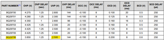
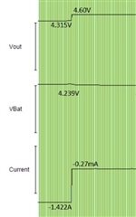
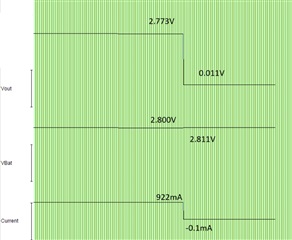
When I discharge my battery and I monitor the voltages and discharge current (through a fixed sense resistor), I see that the UVP is working, but it's not cutting at 2.5V as expected, but at 2.8V - another value on the datasheet, for other P/N from the same family. Here is the setup and the results:
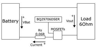
Pins of the IC:

  • V- is connected to the negative pad of the load through a 2k2 resistor
  • VSS is connected to the middle point between the MOSFETs and the sense resistor
  • BAT is connected to the battery positive terminal

The marking on the package of the chip on my boards is "F4", which corresponds to the BQ29706DSER device.

Is it possible that the devices were wrongly programmed for a different UVP voltage?

Best,

Victor

  • Update: I monitored the same voltages and current while charging the battery with a laboratory power supply, with a current limit of 1.4A, and a voltage of 4.6V connected to the terminals of the load (load disconnected).

    The OVP seems to work fine, but also at a different voltage than the stated on the datasheet. On the datasheet it says it should cut the current at 3.85V, but it cuts it at 4.3V (or 4.25V, another OVP value for another P/N from the same family).

    In summmary:

    Expected Measured
    UPV 2.5V 2.8V
    OPV 3.85V 4.3V

    The measured voltages correspond to either BQ29700, BQ29702, BQ29707 or BQ29728, but not to the BQ29706 that I have assembled on our boards. Is this a known issue? Am I overlooking something? What can I do to get the correct UVP and OVP?

    Thank you very much!

    Best,

    Victor

  • Hi Victor, 

    Apologies for the delay and thank you for your patience.
    We are not aware of any issues with the accuracy of our devices, so the IC should match the specs. I think the root cause might be of where you are measuring the signals, maybe you are not considering the drop of your internal circuits (RDSON, etc..). Please refer to the datasheet (https://www.ti.com/lit/ds/symlink/bq2970.pdf) the section 7.2 Test Circuits include how to measure all the protection, as well as 7.3 Test Circuit Diagrams which include the configuration. Please re-try following those steps. 

    Regards, 

    Arelis G. Guerrero