Other Parts Discussed in Thread: UCC2803
Tool/software:
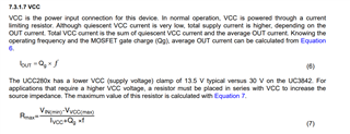
In my case, i have Vaux as 9 to 9.5V. How to calculate Raux since internal zener diode will never be operational as our Vinput is 9V.
Through Webench it says 10ohm.
Tool/software:
In my case, i have Vaux as 9 to 9.5V. How to calculate Raux since internal zener diode will never be operational as our Vinput is 9V.
Through Webench it says 10ohm.