This thread has been locked.

If you have a related question, please click the "Ask a related question" button in the top right corner. The newly created question will be automatically linked to this question.

UCC27714: LLC simulation support with ROHM device

Part Number: UCC27714

Tool/software:

Hlo team,

I'm using UCC27714 for switching LLC converter I faced few issues while testing in the lab, So I want to simulate the circuit in TINA.

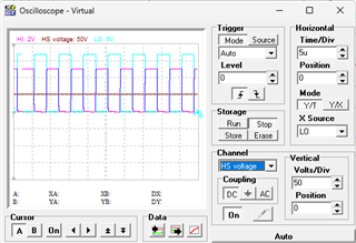
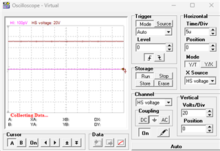
But I'm not getting exact output what I'm expecting that HO & LO should follow the HI & LI signal with 18V.

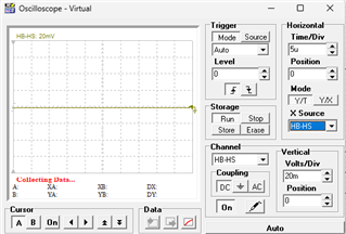
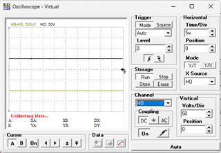
And bootstrap capacitor was not charging up to Vdd voltage, here I'm attaching the .TSM file please correct and revert if any changes required.

Thanks

Umesh D.slum494 ROHM.TSC

  • Hello Umesh,

    I tried running the schematic you attached and I am getting a syntax error. Can you provide a waveform plot of the signals that you have a concern? For the bootstrap cap to charge, the low side FET needs to switch to ground to provide a path for the boot cap to charge. Can you confirm that the low side FET is switching and the HS pin swiches close to ground?

    Regards, 

  • Hello Richard,

    What was the syntax error you are getting. Low side FET signal was as expected i.e.18V. But HS pin is having constant 50V and H0 pin also having constant 50V.

    Could you please verify whether I modelled my FET (SCT3040Kr) correctly or not, in TSM file you have HZ voltage probe right, there I'm getting 400V but if I measure voltage across  Cboot with Multimeter I'm getting -276mv.

    Regards,

    Umesh D.

  • Can you plot the HS voltage, and the HB-HS voltage? We need to confirm the HS is switching to ground, and HB to HS bias is above the UVLO. Confirm the power devices VDS is responding.

    Regards,

  • How to check whether VDS is responding or not?

    Image 1 shows the HS voltage, image 2 shows the HB-HS voltage, and image 3 shows the HO voltage; it is constant at 50V.

  • Hello Umesh,

    I looked at your schematic again and also looked at the SCT3040 datasheet. It does look like you have the correct pin connections according to the datasheet of the ROHM device. If U2 gate to source voltage is 18V as I think you showed on a previous plot, the U2 drain voltage should switch to close to ground. Otherwise there is something with the Mosfet model not correct. The threshold voltage (Vgs) spec is 5.6V so 18V is more than adequate to switch the device.

    Can you try connecting pin 2 to 3 externally in the schematic on the ROHM power FET's, to see if there is something wrong with the kelvin source connection? If the switch node switches to ground, the HB bias can charge which will allow the driver HO to operate.

    Regards,

  • Hello Richard,

    Thank you for the suggestion. I tried what you recommended, but unfortunately, it's still not working.

    When I replace the SCT3040KR with the default MOSFET model in TINA (2N6755), the circuit works fine.

    I noticed that the 2N6755 is a 3-pin device, whereas the SCT3040KR is a 4-pin device. Could there be any specific considerations when using the UCC27714 to drive a 4-pin device like the SCT3040KR?

    I’m facing the same issue on my test board as well. Are there any special layout recommendations for using 4-pin devices?

    Thank you.

  • Hello Richard,

    Is there any update?

  • Hi Umesh,

    Responses will be delayed due to US holiday.

    Our dedicated expert will get back to you shortly.

    Regards,

    Hiroki

  • Hello Umesh,

    Thank you for confirming an alternate FET works OK in the simulation. I am surprised you see the same issue in the actual board. According to the datasheet from ROHM the pin 2 and 3 should be connected internally in the FET. Considerations for using Kelvin source FETs with the driver relate to how the VSS and COM are routed on the board layout. There is an FAQ on this subject regarding using the split ground of the UCC27714, at the link below.

    https://e2e.ti.com/support/power-management-group/power-management/f/power-management-forum/1493915/faq-ucc27714-what-are-the-design-considerations-for-split-ground-half-bridge-gate-driver-in-high-voltage-applications

    You may want to confirm that the ROHM FET does not have some unique concerns regarding the kelvin source connection.

    Regards,