This thread has been locked.

If you have a related question, please click the "Ask a related question" button in the top right corner. The newly created question will be automatically linked to this question.

TPS62801: Logic Interface EN Question

Part Number: TPS62801
Other Parts Discussed in Thread: TPS62088, TPS628503, TPS628511, TPS628513, TPS628501

Tool/software:

Hi expert,

Customer is looking into some of our power sequencing and have a question regarding the Logic Interface EN on two specific power supplies:

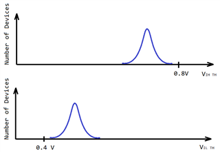
  • TPS62801 → VINH TH = .8V,   VINL TH = .4V
  • TPS62088 → VINH TH = 1V,   VINL TH = .4V


What we currently do not understand is if there is hysteresis/ a Schmitt trigger on these pins. For context, we are using an RC filter to provide the appropriate power sequencing that we will need. It will take over a ms with our RC network for the Enable pin to go from .4V (Logic low) to .8V (Logic High), but if there's not hysteresis or a Schmitt trigger and the pins operate like a digital IO, we may be inadvertently enabling one of the devices over a millisecond before we intended to. 

Could you please clarify how we can expect these pins to behave? Also please let me know if I should submit another request for the other part # TPS62088.

 Thank you!

McKenna

  • Hello McKenna,

    thanks for reaching out in E2E.

    Both devices have a built in hysteresis at the EN pin. For the TPS62088 the EN hysteresis is ca. 200 mV. For the TPS62801 the EN hysteresis is ca. 130 mV.

    The TPS62801 has the so called Smart EN feature implemented, which might impact this use case. On this device the EN has some internal 500 kΩ pull-down resistor, which is only active as long as the device is disabled. The PD resistor is disconnected as soon as the device has started to minimize power losses in the application. For the start-up with an RC filter at the EN this should be no problem, as the RC voltage would rise faster without the PD once the device has started. But care should be taken that the R in the RC is much lower than the 500 kΩ of the internal PD resistor in order to overcome the EN threshold.

    Please also be aware that the EN threshold spec implies some range for parameter variation. That means the threshold might vary a bit from device to device and over temperature. Slow EN ramp-up might result in timing variation. For a more precise timing it would be possible to control the sequencing by some digital logic. Alternatively a device with the so called Precise EN feature could be selected, which has a much tighter EN threshold specification. Devices with Precise EN would be for example TPS628501 and TPS628511 for 1A or TPS628503 and TPS628513 for 3A.

    Best regards,

    Andreas.

  • Hi Andreas,

    Thanks for the help on this, and great point about the PD resistor; we have our R sized such that it shouldn't be an issue. 

    At this point it's much too late in the design process to switch power supplies, Just wanted to make we're accounting for the large variation in start-up times that could occur.


    The hysteresis is still a little unclear to me at the moment. if we have logic low (sub .4V) then we can expect the enable pin to remain low until it reaches .6V? From .6V to .8V the enable pin status will be unknown since it is between the Enable high threshold and the enable low threshold? 

    Thanks!

    McKenna

  • Hi McKenna,

    thanks for the update.

    It is important to interpret these input threshold levels from the statistical perspective. Here is a quick drawing for illustrating the behavior in general but not in accurate numbers:

    When rising the EN voltage from 0 to 0.8V then the EN threshold of all devices is following some statistical distribution. The majority of devices is detecting a high and enabling at let's say 0.7V. When reaching 0.8V the whole population of devices has detected a high with additional margin. So this would be the spec limit for VIH TH because we can be sure that all devices will be enabled at this voltage and above. That's also the reason why it is specified as a minimum voltage level. Once the devices are enabled then the hysteresis takes effect and the distribution for disabling is lower now. So when slowly lowering the EN voltage again, then the majority of devices is detecting a low and disabling at let's say 0.5V. But at 0.4V we can be sure that all devices have disabled with some margin. So this can be the spec limit for VIL TH as a maximum voltage (below they are disabled for sure). To be precise, these distributions also include variation for the specified temperature and VIN corners.

    If you pick a single device from the middle of the distribution, which would represent the majority of the population, then it would enable at 0.7V and above in this illustration and it would disable at 0.5V.and below. So the hysteresis would be 0.2V in this case. There is no undefined state in between.

    I hope this can help to understand the EN threshold spec limits. Let me know if you still have questions, otherwise I would be more than happy if you click resolved to close this thread.

    Best regards,

    Andreas.

  • Hi Andreas

    I have the following remaining question/uncertainty. Can you help clarify?

    "The hysteresis is still a little unclear to me at the moment. if we have logic low (sub .4V) then we can expect the enable pin to remain low until it reaches .6V? From .6V to .8V the enable pin status will be unknown since it is between the Enable high threshold and the enable low threshold? "

    Thanks for your help.

    Best regards,

    Jim B

  • Hello Jim,

    sorry for the late reply, I was not in the office last week.

    The exact threshold of a single device is indeed unknown until the device is getting characterized. But what can be expected from the datasheet limits is that a voltage level of VEN ≤ VIL TH (lower spec limit) will cause a disabled device and VEN ≥ VIL TH (upper spec limit) will cause an enabled device. Static EN voltage levels between upper limit and lower limit should not be used on purpose. But transitions from below lower limit to above upper limit (and vice versa) are allowable due to the built in hysteresis.

    Best regards,

    Andreas.