This thread has been locked.

If you have a related question, please click the "Ask a related question" button in the top right corner. The newly created question will be automatically linked to this question.

TPS7A14: Schematic review

Part Number: TPS7A14
Other Parts Discussed in Thread: TPS7A02

Tool/software:

Hi Team,

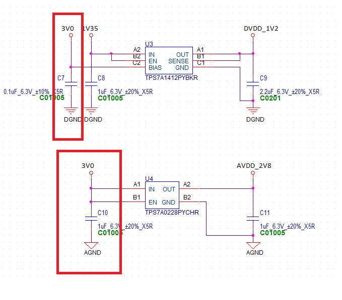
Could you help review below schematic? The 1V2 is for digital voltage and 2V8 is for analog voltage, so the GND is different.

Will this cause any risk? Any suggestion for better performance. It's for PE camera module.

Thank you!

Marc

  • Hi Marc,

    • TPS7A14
      • The values in section 6.3 of the datasheet for the capacitors are effective capacitance, and because of this the minimum requirements are not met. Derating due to temperature, process, and DC bias all need to be considered. 
      • Besides that, the schematic looks good.
    • TPS7A02
      • The output capacitor will likely derate to less than the minimum requirement of 0.5uF due to the DC bias and process tolerance without considering the temperature variation. You may need to bump up the voltage rating if you can find one without going up a case size.

    Regards,

    Nick