


Other Parts Discussed in Thread: TLV4062, TPS61094
Tool/software:
This question is a bit tricky.
I'm planning to use the TPS62842DGR as a second stage DC regulator to generate a 3.3V output.
The first stage is a buck boost regulator that generate the following voltage curve:
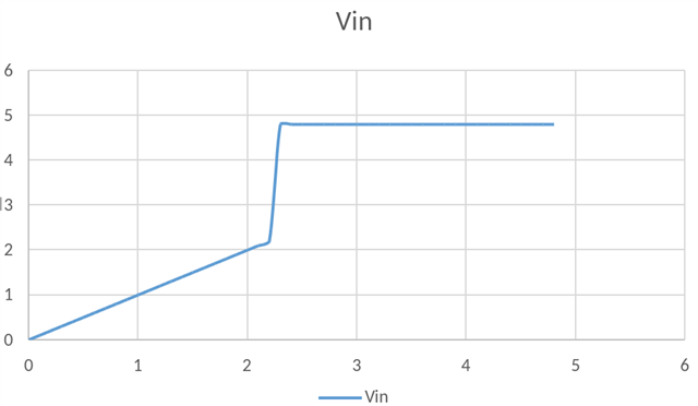
In the system input voltage is below 2.2V, it's working as a buck converter so the Vout of the first power regulator follow the system input voltage and this voltage is visible on the Vin of the TLS62840.
When the system input voltage is above 2.2V, the first power regulator enable its boost converter to regulate Vout to 4.8V. So there's no voltage between 2.2V and 4.8V on Vin of the TLS62840.
I want to only enable the TLS62840 when the input voltage is 4.8V, not when it's below 2.2V, since I don't want to have 2.2V on its Vos pin.
I've studied the datasheet and found this:
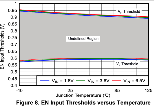
Ok, so I set up a resistor divider bridge (with k = 0.2) for the EN pin. However, the datasheet also contains that the EN pulldown resistor's variability goes from 200kΩ to 450kΩ (page 7) and it's disconnected upon start up when EN is high (page 12, section 8.3.1).
Thus, this makes creating a resistor divider bridge very complex.
If I use the typical value, I'd use a high level resistor of 1.7MΩ so that when Vin = 4.8V, EN is 0.96V and when Vin = 2.2V, EN is 0.44V.
However, if the pulldown resistor is only 200kΩ then I'd get a ratio of only 0.10, making EN = 0.48V for 4.8V as input which is too low to enable the device.
I can also have an external resistor divider, (with say a 100kΩ bottom resistance in parallel to the EN's pull down resistance, making a 66kΩ to 81kΩ final resistance bottom value, and a 245kΩ for the top resistance). In that case, it would work, but the bridge will consume 13µA which is way too much for our application (that's the budget for the MCU).
Also, when the device is enabled, the pulldown is disconnected, thus changing the divider ratio to 0.29 which, if the input voltage falls back to 2.2V, will give a 0.63V value (right into the "Undefined region"), so likely too high to disable the device.
So my question is: Does the graph above for EN input threshold already includes the variability of the pull down resistor and thus don't care about it and take 450kΩ as the only possible for computation? In that case, once the 450kΩ resistor is disconnected, how can the device detect the disabling threshold if the voltage fell to 2.2V since there's no current sink on the bridge anymore?
