This thread has been locked.

If you have a related question, please click the "Ask a related question" button in the top right corner. The newly created question will be automatically linked to this question.

UCC28180: Harmonic debugging issue of UCC28180

Part Number: UCC28180

Tool/software:

Hi TI Team,

When the customer was debugging UCC28180, they encountered harmonics that were difficult to debug. It was very bad. The specific situation is described as follows

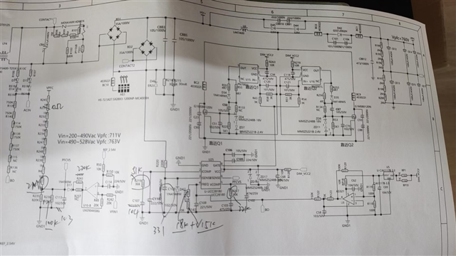
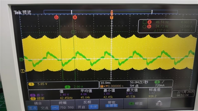
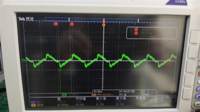
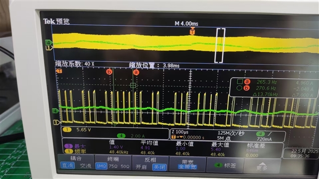
When the input voltage is 480V, that is, when a high voltage is input and a light load is driven, for example, between 10%, 5% and 30%, the PF value and harmonics are relatively poor. Then, when the drive waveform is expanded, it is found that at the intersection, the frequency is unstable and there is a phenomenon of periodic hopping.

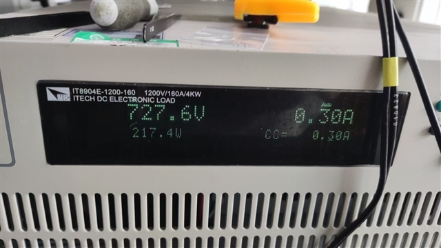
The specific test waveforms, test data and circuit diagrams are as follows:

  • Hello Ken, 

    I agree that the input current waveform is not very good looking under these test conditions. 

    However, if I interpret the Chroma power analyzer display correctly, the 26.648 value is A%, which I believe is % THDi. 
    Assuming that, 27% distortion is not so good, however, the PF equivalent is 0.9654.

    The Chroma meter shows that PF is actually 0.6886, which means that most of the low PF is due to phase-shift from current through X-capacitance in the EMI filter.  
    0.6886/0.9654 = 0.7133, so 0.7133 is the component of PF that is due to phase-shifted X-cap current with respect to the input voltage.

    PF always goes down significantly at very high input voltage and low loads, because much of the AC input current becomes capacitive current rather than load current. 

    The EMI filter is not shown in the schematic diagram, but reducing the amount of X-cap will improve PF.  Also reduce the Cin value (C883 and C885) from 2uF to 1uF or lower, which will also help reduce THD as well as less phase shift. 

    The maximum power level of this PFC is not provided.  I will assume that the eLoad display of 217.4W represents about 10% of full load. 
    At high voltage and light load, the voltage on the VCOMP pin of UCC28180 will be close to ~0.5V.   

    The PWM ramp slope follows the equations on page 31 of the data sheet and VCOMP near 0.5V results in M2 = ~0V/us.  

    Especially if ripple on VCOMP causes Vvcomp to fall below 0.5V, the PWM slope become 0 and there will be no PWM pulses. 
    So I believe that the missing PWM pulses in your last screenshot are simply skipped pulses due to VCOMP voltage too close to the internal 0.5V threshold. 
    There is no harm in skipping some pulses.  
    I think even more pulses will be skipped at even lighter load and no-load condition. 

    Regards,
    Ulrich