Tool/software:
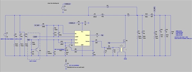
I'm currently working on a peak current mode control boost converter. I recently joined the company that originally designed it, and I'm using a UCC28C43D controller.
As I review the schematics, I've noticed some unusual design choices. For instance, instead of a shunt resistor, the design uses a current transformer—likely to avoid heat dissipation issues associated with shunt resistors. Normally, when using a current transformer to sense switch current, it's placed on the drain of the MOSFET to avoid interfering with the gate-source voltage that controls the MOSFET. However, doing this typically requires a differential input PWM controller with CS+ and CS- pins to accurately read the current signal. The UCC28C43D only has a single CS pin referenced to ground.
Additionally, in my previous designs, I used the gate-to-source voltage along with an RCD network to implement slope compensation, following Ray Ridley’s approach. I’m not particularly comfortable with using the RT/CT pin for this purpose, as is done in this design. I’d like to make some changes, but convincing some of the more resistant team members may be challenging.
What are your thoughts on using a current transformer on the source of the MOSFET in a design based on the UCC28C43D?
Thanks