This thread has been locked.

If you have a related question, please click the "Ask a related question" button in the top right corner. The newly created question will be automatically linked to this question.

BQ25628E: VSYS and VBAT spike following switching on TS_ADC

Part Number: BQ25628E

Tool/software:

Hi,

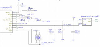
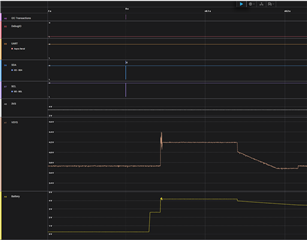
I've noticed some weird behaviour when I switch on the ADC for measuring TS_ADC. I don't currently have a battery or TS attached, so I'm not sure if that's relevant to the issue. 

Chip markings show:

BQ628E
TI 478
A63 LG3


  • Hi Stephen, 

    Thanks for reaching out via E2E. 

    Upon review of the waveform it appears SYS voltage is overshooting in response to battery voltage increase. You mention you are switching on the ADC, are you sending any other I2C writes at that time? Based on the waveform it appears charge is being enabled and VBAT is quickly rising to full charge voltage since you do not have a battery attached to the IC. 

    Generally speaking overshoot observed at SYS and BAT pins due to enabling charge with no battery connected is not unexpected. 

    If you are looking to evaluate TS and TS_ADC functionality I do recommend you have an NTC connected or a 10kohm resistor in place of the NTC to simulate the NTC in normal temperature range. 

    Best Regards,

    Garrett 

  • Hi Garrett,

    The main question I suppose is why does VSYS and VBAT do anything when the only command is to enable the ADC (on a single channel of TS_ADC). I'm sending [ 0xD0 , 0xFB ]. I'd understand if the ADC were somehow connected to the battery, but the TS_ADC is leaving me confused. 

    Stephen

  • Hi Stephen, 

    Thank you for your response. Please see my comments below. 

    VSYS is increasing in response to VBAT increasing. Due to the architecture of the charger IC during charging VSYS will be above VBAT. What remains unclear at this time is why VBAT is increasing in your test. I have tested sending REG0x26 = 0xD0 and REG0x27 = 0xFB and it does not cause VBAT to increase. 

    Do you have charge enabled during your test? If so can you please try disabling charge via REG0x16 bit 5 = 0b then try turning on the ADC. In this case I would not expect VBAT to increase. 

    Additionally,  I notice in your schematic you have capacitors connected at TS. This is not recommended as no capacitance is necessary at TS pin. I am wondering if enabling the TS ADC channel while having capacitors on TS, but no NTC connected is causing TS voltage to briefly be within allowable range to allow charge to start. This could be what is leading to VBAT increase. 

    Best Regards,

    Garrett 

  • Hey Garrett,

    It certainly looks like it was related to the TS capacitor. We had added some capacitance to filter ESD spikes, but upon reflection the values are much too big considering the pulsing of TS_BIAS.