Other Parts Discussed in Thread: STRIKE
Tool/software:
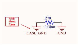
I am using the LM3671MF-3.3/NOPB in a circuit for my company as a 3.3V regulator. In this design we have a USB 2.0 connector that uses Type A USB. We have the casing of the USB connected directly to our digital ground (same ground that our LM3671MF-3.3/NOPB uses).
When I provide an electric shock to the USB casing, the 3.3V regulator gets damaged and no longer works. When I replace the 3.3V regulator with a new one the board operates as normal.
As you can see we have an ESD problem and it is affecting quite a few of our boards which results in unhappy customers. I have tried the typical solution of connecting a TVS diode directly across the input of the 3.3V regulator. This resulted in what seemed to be a more reliable solution, but still after shocking a few times the 3.3V regulator eventually fails. The tvs diode I used was the SP0502BAHTG. I tried both a unilateral and bilateral (by connecting 2 SP0502BAHTG's in series) connection for my TVS diode and it failed when shocking the USB case.

What I believe is the problem is that the LM3671MF-3.3/NOPB has an absolute max voltage of 5.5 volts and we input 5 volts into it which does not give us a big margin to work with. This means that if the SP0502BAHTG did its job perfectly it has a max clamping voltage of 8.5V which is 3 volts higher than the absolute max which I believe is causing damage. The hard part is there isn't really a TVS / Zener diode that meets the criteria to clamp at 5.5 volts, yet have a reverse standoff voltage of 5 volts. Even if there were such a diode I am not sure that I would be comfortable using it since there is only 0.5V margin between shorting the diode and the diode being an ESD protection.
Do you have any good solutions to ESD problems with the LM3671MF-3.3/NOPB? Have you seen this problem before?
Thanks,
Trevor