This thread has been locked.

If you have a related question, please click the "Ask a related question" button in the top right corner. The newly created question will be automatically linked to this question.

LM25184EVM-S12: [LM25184EVM-S12] Increasing soft start capacitor = lost Vout regulation

Part Number: LM25184EVM-S12
Other Parts Discussed in Thread: LM25184-Q1

Tool/software:

Hi,

i'm trying the evaluation board LM25184EVM-S12, with default configuration and it's ok, very good results.

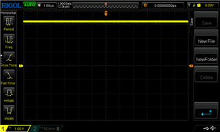
24V In, 12.33V Out, 125 mA

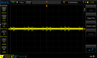
Than I increased soft start capacitor from 47 nF to 470 nF and Vout regulation was not stable over the time, changing of tens of millivolt.

So I mounted a reasonable value of 100 nF and for a good period of time the Vout was stable.

Today, in the same conditions, the board worked good for a while, then was not able to keep regulation with same load, the output voltage dramatically changes over the time, reducing until 0 V after few seconds.

So I mounted again a 47 nF soft start capacitor and now the Vout is stable.

I can't understand the correlation between soft start capacitor and Vout regulation. Am I missing something?

Thanks

  • Hi Marco,

    LM25184-Q1 has an adjustable soft start time that can be controlled by a capacitor connected at the SS/BIAS pin. The higher the capacitor, the longer the time it take for Vout to reach regulation. Soft start time can be calculated with the equation below. On the other hand, this should not affect regulation and/or stability. Could you please send waveforms of Vout when this happens? Please take them with the parameters shown below

    1. (Vout-GNDS) DC coupledm ~10ms/div, (SS-GND), (SW-GND), (VIN-GND)

    2. (Vout-GNDS) AC coupled ~100us/div, (SS-GND), (SW-GND), (VIN-GND)

    The time scales are just estimations; you can judge what are the best in order to show the variations on Vout (especially on AC coupled)

    Thank you

  • Hi,

    I'll share the waveform when the problem will appear again.

    Now I can describe it: SW waveform looks good, then the input current start to change and decreases, SW waveform keep the exact shape buy the frequency decreases slowly and so do the output voltage. A slow process when everything decreaes to zero, and SW frequency is very very low to few kHz (not audible), with the usual shape.

    I only changed SS capacitor in a totally default evm board.

    Do you have the possibility to replicate this in your labs? 

  • Hi Marco,

    Please expect a delay in responses due to US holiday.

    Thank you.  

  • Hi Marco,

    I dont have bench capability as of now. I will wait for the waveforms so I we can judge better.

    Thank you

  • Hi

    I made some changes on the EVM to get my target of 28V out and i'm happy with the result.

    Anyway there is still the problem with the SS capacitor.

    With 47nF all is fine, with 100 nF there is a Vout drift over the time of tens of millivolt, moreover at the starting.

    And when I power on the board, the initial Vout is always different, then drift. This don't happen with 47nF.

    So the correlations is here, no doubt about. 

    1) SW - 28V IN, 28.8V OUT

    2) VOUT AC - 28V IN, 28.8V OUT

    3) VIN AC (IC input pin) - 28V IN, 28.8V OUT

    4) SS DC - 28V IN, 28.8V OUT

    5) SS AC - 28V IN, 28.8V OUT

    Here the noise is due to probe wire, is not on that pin, is a background noise

  • Hi Marco,

    Thank you for sharing the waveforms. Vout shows a ~70mVpkpk of AC ripple, this means a ripple of 0.07/28=0.25% which is pretty low and acceptable. SW, VIN and SS waveforms look good too. Are these waveforms with 100nF? The small variations on Vout (I guess that is what you mean with 10mV drifts) are probably coming from the HF harmonics from leakage inductance when the MOSFET turns off, but it shall not affect regulation and switching.

    Thank you

  • Hello,

    yes this waveforms are with 100 nF and also for me looks good, but the problem is still here.

    With drift I mean a slow increment or decrement of Vout with the time. 

    Now, after more test, I think is related to temperature, like SS capacitor affect the termal compensation. 

    Just an example, 47 nF and 30 minutes run time:

    Vout_start = 28.85 V, Vout_final = 28.85V (Vout_min = 28.83 V, Vout_max = 28.83 V), so pretty stable

    470 nF and 30 minutes run time:

    Vout_start = 28.6 V, Vout_final = 28.9 V (Vout_min = 28.4 V), there is 0,3 V drift, unacceptable!

    In this case the voltage start then decrease until its minimum value than start to increase until max value.

    This don't happen with 47 nF, test made in same conditions, same variables.

    Can I do something to mitigate this effect? 

    R_FB and R_TC are 143K and 576K, same values in both runs. 

  • Marco,

    This is something new that needs to be investigated. SS cap should not affect Vout regulation at all. Is there any reason why you need to use 470nF? If not, I recommend using a 47nF.

    Thank you

  • Yes, we need 100 ms of soft start, is mandatory.

    So I'll play a little with Rtc value to compensate a bit more for this drift. Please let me know if you have any news.