This thread has been locked.

If you have a related question, please click the "Ask a related question" button in the top right corner. The newly created question will be automatically linked to this question.

LM27761: Help

Part Number: LM27761
Other Parts Discussed in Thread: LM2776

Tool/software:

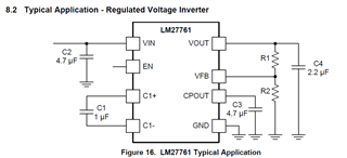
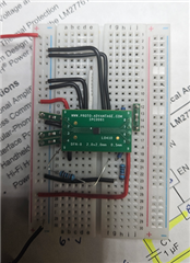
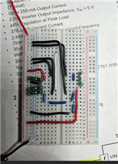
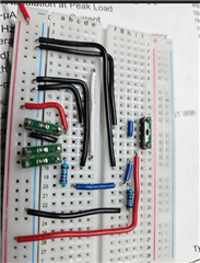
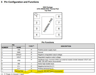
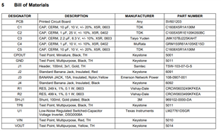
Hi, I am new to the forum and am unable to get the LM27761 to work properly. R1 is 120K ohms, R2 is 100K ohms. I am using surface mount capacitors per the below schematic. They are all in the 0603 package and a combination of X7R and X5R low ESR, no greater than .03 ohms. Each component is on an adapter board which was professionally soldered on a hot air workstation. I have wired the circuit on a breadboard basically with very short or no leads at all. All 4 of the adapter thermal pads are tied to ground. I cannot get the output to be greater than -.35 volts. EN is tied directly to VIN. Any help would be appreciated. 

  • I wanted to add more info in order to help facilitate a solution. I am running a 10amp DC power supply to test the circuit set at 3.3 volts. I measured each capacitor on the adapter board. Here is that info as well as the data sheet voltage rating:

    C1: 1.1uF, esr of .28 ohms rated for 6.3 volts

    C2: 5.3uF, esr of .38 ohms rated for 6.3 volts

    C3: 5.5uF, esr of .38 ohms rated for 10 volts

    C4: 2.4uF, esr of .34 ohms rated for 6.3 volts

    I went ahead and tested each pin to ground with a volt meter. Here is that info:

    Pin1: 3.3 volts

    Pin3: -.89 volts

    Pin4: -.34 volts

    Pin5: -.16 volts

    Pin6: 3.3 volts

    Pin7: -.31 volts

    Pin8: 2.62 volts

    Here are some mor pictures of the board without the chip installed. What am I missing here for this to work properly.

  • Hi Stephen,

    Thanks for using E2E.

    On your setup it is not easy to see if the connections are correct and I don't know if the setup is working at all.

    Some questions:

    • Have you checked the device without load?
    • Do you see a different behavior if you supply a higher voltage at the Vin pin?

    Best regards,

    Sepp

  • Pin 1will be the top left pin which is vin and a cap to ground.. you can follow down that row to pin 4 and then over to pin 5 and up to pin 8. I do have an output but it's only -.35 volts. It's a clean signal when I scoped it. I will try increasing vin to 4 volts to see what effect it has on the output. 

  • As i increase the input voltage, the output increases as well. One other thing, I have no load connected to this board. Just trying to get a reasonable output based on my resistor network. 

  • Hi Stephen,

    The setup in general looks ok but do you have connected the thermal pad to GND?

    Otherwise I would recommend to use our EVM https://www.ti.com/tool/LM27761EVM for testing this device.

    Best regards,
    Sepp

  • Josef,

    Thanks for the reply. Yes the adapter board came with the thermal pad connected to 4 pins. They are all tied to ground. They are shown in the above picture (black wires). I have that evaluation board on order and it should come in today. I was also looking at the webench power design tools for that chip. There is only a design for the LM2776 that I found. I am not sure that I used the recommended caps since that chip was not in webench. Can you recommend part numbers for the caps? The other questions I have is it even possible to get a high frequency switching chip like this to work on a breadboard? Any help would be appreciated.

  • Hi Stephen,

    You will find recommended parts in the User's Guide for the EVM:

    To be honest, I don't think that a breadboard will work for this type of devices.

    Best regards,
    Sepp

  • Totally agree, thanks for the help