Tool/software:
Hello, can you please help me with this BQ25703A charger chip?
I am trying to get it working, but I can't read any of the voltage or current values.
here is my arduino source code, I'm using this library to read/write the registers: https://github.com/Lawmate/BQ25703A/tree/master
#include <Arduino.h>
#include <Wire.h>
#include "i2c_scanner.h"
#include "usb_pd.h"
#include "io_expander.h"
// Define I2C pins
const int I2C_SDA_PIN = 1;
const int I2C_SCL_PIN = 0;
#include <Lorro_BQ25703A.h>
#define BQ25703ADevaddr 0x6B
//Initialise the device and library
Lorro_BQ25703A BQ25703A;
const byte Lorro_BQ25703A::BQ25703Aaddr = BQ25703ADevaddr;
//Instantiate with reference to global set
extern Lorro_BQ25703A::Regt BQ25703Areg;
void setup() {
Serial.begin(115200);
while (!Serial); // Wait for serial port to connect (optional)
Serial.println(F("\nSystem Booting Up..."));
// Initialize I2C bus - This is critical and should be done once.
// The BQ25703A init function will use these pins if specified,
// or assume Wire is already configured if pins are passed as -1 (default in charger.h)
// For clarity, bq25703a_init can take these pins.
Wire.begin(I2C_SDA_PIN, I2C_SCL_PIN);
Serial.print(F("I2C Initialized with SDA: ")); Serial.print(I2C_SDA_PIN);
Serial.print(F(", SCL: ")); Serial.println(I2C_SCL_PIN);
Serial.println(F("Scanning I2C bus..."));
scan(); // Call your I2C scanner function
delay(100);
setup_usb();
//setup_io_expander();
//Set the watchdog timer to not have a timeout
BQ25703Areg.chargeOption0.set_WDTMR_ADJ( 0 );
BQ25703A.writeRegEx( BQ25703Areg.chargeOption0 );
delay( 15 );
//Set the ADC on IBAT and PSYS to record values
//When changing bitfield values, call the writeRegEx function
//This is so you can change all the bits you want before sending out the byte.
BQ25703Areg.chargeOption1.set_EN_IBAT( 1 );
BQ25703Areg.chargeOption1.set_EN_PSYS( 1 );
BQ25703A.writeRegEx( BQ25703Areg.chargeOption1 );
delay( 15 );
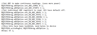
//Set ADC to make continuous readings. (uses more power)
BQ25703Areg.aDCOption.set_ADC_CONV( 0 );
BQ25703Areg.aDCOption.set_ADC_START( 1 );
//Set individual ADC registers to read. All have default off.
BQ25703Areg.aDCOption.set_EN_ADC_VBUS( 1 );
BQ25703Areg.aDCOption.set_EN_ADC_PSYS( 1 );
BQ25703Areg.aDCOption.set_EN_ADC_IDCHG( 1 );
BQ25703Areg.aDCOption.set_EN_ADC_ICHG( 1 );
BQ25703Areg.aDCOption.set_EN_ADC_VSYS( 1 );
BQ25703Areg.aDCOption.set_EN_ADC_VBAT( 1 );
//Once bits have been twiddled, send bytes to device
BQ25703A.writeRegEx( BQ25703Areg.aDCOption );
delay( 15 );
}
unsigned long lastChargerStatusTime = 0;
void loop() {
//handle_io_expander();
BQ25703Areg.aDCOption.set_ADC_START( 1 );
BQ25703A.writeRegEx( BQ25703Areg.aDCOption );
delay( 15 );
Serial.print( "Voltage of VBUS: " );
Serial.print( BQ25703Areg.aDCVBUSPSYS.get_VBUS() );
Serial.println( "mV" );
delay( 15 );
Serial.print( "System power usage: " );
Serial.print( BQ25703Areg.aDCVBUSPSYS.get_sysPower() );
Serial.println( "W" );
delay( 15 );
Serial.print( "Voltage of VBAT: " );
Serial.print( BQ25703Areg.aDCVSYSVBAT.get_VBAT() );
Serial.println( "mV" );
delay( 15 );
Serial.print( "Voltage of VSYS: " );
Serial.print( BQ25703Areg.aDCVSYSVBAT.get_VSYS() );
Serial.println( "mV" );
delay( 15 );
Serial.print( "Charging current: " );
Serial.print( BQ25703Areg.aDCIBAT.get_ICHG() );
Serial.println( "mA" );
delay( 15 );
Serial.print( "Voltage of VSYS: " );
Serial.print( BQ25703Areg.aDCIBAT.get_IDCHG() );
Serial.println( "mA" );
delay( 15 );
Serial.println("----------------");
Serial.println();
Serial.println();
delay(10); // Small delay between reads to ensure bus stability, adjust if needed
delay(5000);
}This code is basically the readVoltages example from the library
Here is the output of the serial console:
System Booting Up...
I2C Initialized with SDA: 1, SCL: 0
Scanning I2C bus...
Scanning...
I2C device found at address 0x27  !  -> PCF IO Expander
I2C device found at address 0x28  !  -> USB_PD
I2C device found at address 0x40  !  -> INA3221 ADC
I2C device found at address 0x6B  !  -> Charger
I2C device found at address 0x75  !  -> Buck converter
done


Initializing STUSB4500...
Connected to STUSB4500!
STUSB4500: Set to request 9V if possible

Voltage of VBUS: 3200mV
System power usage: 0.00W
Voltage of VBAT: 2880mV
Voltage of VSYS: 2880mV
Charging current: 0mA
Voltage of VSYS: 0mA
----------------
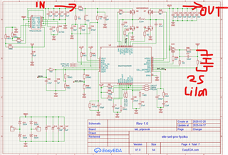
Anyone knows what's the problem? Could it be a hardware issue? The chip is detected correctly by the I2C scanner so it should be working. There is 5V on the VBUS input, but the ADC isnt reading anything