This thread has been locked.

If you have a related question, please click the "Ask a related question" button in the top right corner. The newly created question will be automatically linked to this question.

LMZ13610: Inquiry on how to verify device failues

Guru 11150 points
Part Number: LMZ13610

Tool/software:

Hello,

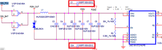
My customer is producing a board that uses LMZ13610 in the power input stage.

They use the following method to determine if the LMZ13610 is defective before powering up.

They measure the resistance of the VIN pin before and after PCB assembly, and if it is significantly lower than the average value (tens of K to hundreds of K ohms), they judge it as defective.

Is this method of determining the device defect valid?

Thank you.

JH

  • Hi JH,

    I do not believe that this value is specified in the datasheet, and thus this would not be a correct assessment of the functionality of the part. I also would not say that the VIN pin resistance is the only deterministic attribute of the device to evaluate its functionality.

    TI outlines the performance of the device through the datasheet. If the device is being used in an acceptable way as shown by the datasheet, the device should operate within the datasheet's specifications. If it is determined that the device does not operate within datasheet parameters but is in an acceptable application, then that device can be considered defective.

    Hope this helps,

    Joshua Austria

  • Hi Joshua,

    Thank you for your reply.

    The customer has an additional question.

    They believe that measuring the resistance of power ICs is a very common way to check for product defects.

    Is the reason you don't recommend measuring the VIN resistance of the LMZ13610 because there is no reference value for this resistance value, or is there something unreliable about the resistance measurement itself?

    Regards,

    JH

  • Hi JH,

    Yes. We don't have a reference value for this resistance that we can share. Additionally, it could be that a part is defective in other ways that don't affect the VIN pin resistance. This is just a cautionary note, but of course the customer can continue checking the parts in this way should they choose to.

    Thank you,

    Joshua Austria

  • Hi Joshua,

    Thank you for your kind reply.

    The customer has question about the symptom he experienced when measuring the VIN resistance of the LMZ13610.

    When they measured the VIN resistance before powering up a few LMZ13610s, it was in the tens of ohms (with an average value of tens of Kohm).

    When they powered up the devices, it worked fine, and when they re-measured the VIN resistance, it changed to tens of Kohm.

    Could you please give them some advice on what could be causing this symptom for the LMZ13610?

    Regards,

    JH

  • Hi Joshua,

    Any updates on the customer's further inquiry?

    Thanks,

    JH

  • Hi JH,

    I believe I will need some more items to be answered before understanding the issue fully.

    How are they measuring the impedance of the VIN pin? Were the IC's populated on a board when measuring VIN resistance? Please also note if my understanding is correct. The part has a certain impedance on VIN before powering on. Once they are powered on, the impedance increases?

    Thank you,

    Joshua Austria

  • Hi Joshua,

    Here are the customer's responses.

    How are they measuring the impedance of the VIN pin?

    The customer is using the LMZ13610 at the system power input and measured the resistance between VIN pin and GND pin of the input connector.

    Were the IC's populated on a board when measuring VIN resistance?

    Yes.

    The part has a certain impedance on VIN before powering on. Once they are powered on, the impedance increases?

    Before power is supplied, most products measure around 28 kOhm.

    Some parts measure several kOhm to several ohm. When re-measuring after power is turned on/off, the parts measure around 28 kOhm.

    Thanks,

    JH

  • Hi JH,

    Thank you for confirming. Please request that they send over the schematic and layout that they are utilizing the device in. 

    It may be helpful to look at the application to determine it's validity. 

    Do the parts that measure significantly less than 28kOhm before the first power on experience any issues once they are powered on? Is the customer seeing any issues with the part performance when compared to the parts with a consistent 28kOhm resistance?

    Thank you,

    Joshua Austria

  • Hi Joshua,

    Please review the circuit diagram and layout below.

    1401.schematic1.pdf1401.layout.pdf   

    Do the parts that measure significantly less than 28kOhm before the first power on experience any issues once they are powered on? Is the customer seeing any issues with the part performance when compared to the parts with a consistent 28kOhm resistance?

    When powering up components that measure significantly lower than 28kOhm before the first power-up, they are divided into those that function normally and those that do not produce any output.

    Thank you.

    JH

  • Hi JH,

    Thank you. I will review this and provide comments by the end of the week.

    Best,

    Joshua Austria

  • Hi Joshua,

    Are there any updates?

    Thanks,

    JH

  • Hi JH,

    What is FGND connected to? 

    Additionally, is there an electrolytic on input? An under-damped filter on input can cause damage to any buck converter, as the inductive ring from the input filter can cause out of spec operation. Please see this application note for more details: www.ti.com/.../snva489c.pdf

    Thank you,

    Joshua Austria

  • Hi Joshua,

    What is FGND connected to? 

    As shown below, FGND is connected to the screw hole and is also connected to GND via BEAD.


    Additionally, is there an electrolytic on input? An under-damped filter on input can cause damage to any buck converter, as the inductive ring from the input filter can cause out of spec operation. Please see this application note for more details: www.ti.com/.../snva489c.pdf

    There is no electrolytic capacitor on input, and the input circuit shared above is all there is.

    Thanks,

    JH

  • Hi JH,

    Thanks for noting FGND. 

    I see, the capacitors on GND and input connected to FGND through a ferrite bead and a capacitor do cause some concern for me. 

    Is this meant as some sort of common mode filter? Is this for isolation? In either case, this part was not designed to have a ferrite bead connection between input and ground.

    My recommendation would be to remove these capacitors and to add the electrolytic on input as this is a critical component for any filter on input. Then check if the customer is still experiencing the input impedance issue as before.

    Thank you,

    Joshua Austria

  • Hi Joshua,

    As you mentioned, are the capacitors to be removed the ones shown below?

    Thanks,

    CH PARK

  • Hi,

    Yes, those were the capacitors I was concerned about that connected a ferrite bead between input and ground together.

    Thank you,

    Joshua Austria