This thread has been locked.

If you have a related question, please click the "Ask a related question" button in the top right corner. The newly created question will be automatically linked to this question.

BQ25672: Always no charging current (CC mode & No Fault)

Part Number: BQ25672

Tool/software:

Dear team,

My English is not good, but I will try to explain my issue.

We have a case that uses BQ25672, the battery is 3S(18650). My power supply is 24V(LRS-350-24 of MEAN WELL)

It sometimes has no charging current for a long time(Current is 0mA), but sometimes it can work(Current is about 1500mA)

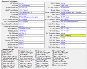
The following is the register value read by the MCU when the current is 0

REG00_Minimal_System_Voltage=0x0B(2750mV)
REG03_Charge_Current_Limit     =0xA0(1600mA )
REG05_Input_Voltage_Limit         =0xDC(22000mV)
REG0A_Re-charge_Control = 0xA3
REG0F_Charger_Control_0 = 0xA2
REG0F_Charger_Control_1 = 0x85
REG0F_Charger_Control_2 = 0x40
REG0F_Charger_Control_3 = 0x00
REG0F_Charger_Control_4 = 0x01
REG0F_Charger_Control_5 = 0x1E
REG1B_Charger_Status_0  = 0x0F
REG1B_Charger_Status_1  = 0x6A
REG1B_Charger_Status_2  = 0x01
REG1B_Charger_Status_3  = 0x00
REG1B_Charger_Status_4  = 0x00

REG20_FAULT_Status_0   = 0x00
REG21_FAULT_Status_1   = 0x00
REG26_FAULT_Flag_0      = 0x00
REG27_FAULT_Flag_1      = 0x00

REG2E_ADC_Control        = 0x80
REG33_IBAT_ADC            = 0mA
REG3B_VBAT_ADC          =10942mV


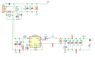
The following is the schematic


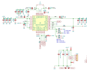
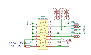
The pin6 of SW3 is connected to P_QON, the pin7 of SW3 is connected to PROG and the pin8 of SW3 is open circuit


Which register values ​​need to be adjusted? Is there an error in the circuit diagram?

Could you help check this case? Thanks.

Best Regards,

Ken
  • Hi Ken,

    I see no obvious errors on the schematic.  The PROG pin is only read at power up (meaning after both VBUS and VBAT have fallen below and then rise above their respective UVLO voltages).  So you cannot dynamically change between 1S and 3S with the PROG pin.  I also assume your input voltage is always greater than your final battery voltage, VREG, because BQ25672 is a buck only charger.  Also, I saw the watchdog timer is set to 40s.  If the watchdog timer expires, many registers reset to default values.  Does your software periodically write to the watchdog timer bit? Lastly, can you repeat what you did to get the charger to not change and then perform 1 read of the registers?  I need to see the status and fault registers from 0x1B to 0x27 immediately after the fault as these registers clear after being read.

    Regards,

    Jeff

  • Hi Jeff,
    Thanks for the reply. Yes, I have written to the watchdog timer bit every 3 seconds.
    I found it has some fault flags when it starts without a battery.

    The following is the register value the first time read when the charger starts without any register set.

    REG1B_Charger_Status_0 = 0x2F
    REG1C_Charger_Status_1 = 0x0A
    REG1D_Charger_Status_2 = 0x01
    REG1E_Charger_Status_3 = 0x00
    REG1F_Charger_Status_4 = 0x00
    REG20_FAULT_Status_0    = 0x20
    REG21_FAULT_Status_1    = 0x00
    REG22_Charger_Flag_0     = 0xAF
    REG23_Charger_Flag_1     = 0x92
    REG24_Charger_Flag_2     = 0x50
    REG25_Charger_Flag_3     = 0x10
    REG26_FAULT_Flag_0       = 0x20
    REG27_FAULT_Flag_1       = 0x40

    The following is the second read register value.

    REG1B_Charger_Status_0 = 0x2F
    REG1C_Charger_Status_1 = 0x0A
    REG1D_Charger_Status_2 = 0x01
    REG1E_Charger_Status_3 = 0x00
    REG1F_Charger_Status_4 = 0x00
    REG20_FAULT_Status_0    = 0x20
    REG21_FAULT_Status_1    = 0x00
    REG22_Charger_Flag_0     = 0x20
    REG23_Charger_Flag_1     = 0x00
    REG24_Charger_Flag_2     = 0x00
    REG25_Charger_Flag_3     = 0x00
    REG26_FAULT_Flag_0       = 0x00
    REG27_FAULT_Flag_1       = 0x00

    I wonder why the charger has some fault flags? How do I fix it?

    Best Regards,

    Ken

  • HI Ken,

    The first read reports:

    and the second read reports:

    So the battery voltage is higher than VREG*1.05%.  What is your VREG setting REG0x01-0x02?  Was this data taken when there is no battery attached?    

    Regards,
    Jeff

  • Hi Jeff,

    I can't see the second read reports.
    Yes, the first and second readings were without the battery connected.

    My usage steps
    1. Turn on the power of the charger
    2. Insert the battery
    So I found some fault flags when I turned on the power before inserting the battery. (VBAT_OVP)

    The REG0x01-0x02 = 0x04EC(1260)


    Best Regards,
    Ken
  • HI Ken,

    BATOVP is expected when no battery or open pack protector FET and only the minimum BAT pin capacitance (~20uF before derating) is installed.  To prevent either:

    1. disable charge with CE bit or pin when battery is removed

    2. allow the TS fault to disable charge when the battery and its thermistor are removed

    3. add 200uF capacitance on BAT

    Regards,

    Jeff