This thread has been locked.

If you have a related question, please click the "Ask a related question" button in the top right corner. The newly created question will be automatically linked to this question.

TPS25751EVM: PDコントローラー評価キットのカスタムボードレビュー願い

Part Number: TPS25751EVM
Other Parts Discussed in Thread: TPS25751,

Tool/software:

Dear Texas Instruments Support Team,

I am planning to design a dedicated UPS power supply circuit for the Raspberry Pi 5 that incorporates a PD controller.

In the intended use case, no data communication is required — the device will operate purely as a power source.

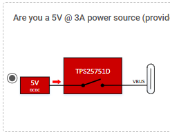
Since the Raspberry Pi 5 requires a relatively high power supply of 5V/5A, which is beyond the standard PD profiles,
I was previously advised in a separate E2E thread to consider the TPS25751, which has led me to this point.

Ideally, I would like to first obtain the TPS25751EVM evaluation kit to verify functionality. However,
since it is currently out of stock everywhere, I am considering building a custom board based on the datasheet.

If possible, I would greatly appreciate your assistance in reviewing the schematic once it is complete.

As an initial question — I believe that the TPS25751EVM uses the TM4C123GH6PMTR (ARM microcontroller)
to serve as a bridge (UART/I²C) for simple EEPROM programming via the GUI tool.

Since the firmware for the ARM microcontroller does not appear to be publicly available,
I am considering writing the PDO profile directly to the CAT24C512WI-GT3 (EEPROM) using a binary file writer.

If this understanding is correct, I assume that the TM4C123GH6PMTR microcontroller is not required in my implementation.
Could you please confirm whether this is the case?

Please note that, as I am not fluent in English, this message was prepared with the assistance of ChatGPT.
I apologize in advance for any unclear expressions and appreciate your understanding.

Best regards,
Yuki Ojima

  • TI-US is closed today. Please allow a delayed response to your query.

    In general, you could use any host adapter (like, aardvark) to program the EEPROM, but I'll let my team review the post and confirm.

  • Dear Praneet Kumar,

    I apologize for sending multiple inquiries in succession.

    Based on the document below, I have created a binary sequence intended to be appended to the .bin file generated by the USBCPD Application Customization Tool, specifically for register 0x32. I would greatly appreciate it if you could review it.

    This binary is planned to be added to the end of the .bin file generated by the tool. Unused fields are zero-padded.

    [Configuration Details]

    Use PDO1

    Use PP_EXT1

    Maximum Voltage: 5V

    Maximum Current: 5A

    [Reference Document]
    www.ti.com/.../slvuc05a.pdf

    [USBCPD Application Customization Tool Settings]

    1) 


    5) No USB data is being used
    7) No
    8) No
    9) No
    10) No

    [Constructed Binary]
    32 01 02 00 00 F4 91 01 00 00 00 00 00 00 00 00 00 00 00 00 00 00 00 00 00 00 00 00 00 00 00 00

    I apologize for the inconvenience and greatly appreciate your support.

    Best regards,
    Yuki Ojima

  • I am not sure why padding zeros would help here. FW will limit max current to 3A. You can setup to use external switch as you are planning and make sure the switch can allow 5A. However the PDO message will only show 3A.