This thread has been locked.

If you have a related question, please click the "Ask a related question" button in the top right corner. The newly created question will be automatically linked to this question.

TIDM-02013: TIDM-02013

Part Number: TIDM-02013
Other Parts Discussed in Thread: C2000WARE, SFRA, SYSCONFIG

Tool/software:

Hi,

We're working with the TIDM-02013 reference design, trying to use it as a baseline for an EV charging product.

For the validation process, we are using the board's reference documentation, which is available on the website.

We succeeded in validating the CLLLC stage, but are having problems validating the PFC stage.

We are following the procedures outlined in the document.

This is our test setup:


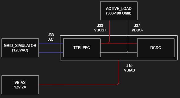
# ISSUE1 - The simulated plant for the PFC is not included in the project


In Lab 2, a graph shows how a simulated plant is used to compute the initial current controller. However, in the C2000Ware_DigitalPower_SDK_5_05_01_00 project, there is no syscfg file, so we cannot use any simulated plant.

We tried the compensator that was specified in the documentation.

K=0.35, Fz=0.03kHz

However, the system triggers an overcurrent trip when the inrush current relay (lab2, current loop DC) is closed with an input voltage of 50 V and a load of 500 Ω is connected.

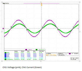
Capture here (CH1:pwm, CH2:dc_link, CH3:current, CH4:dc_in):


We tested several controllers and achieved stability with the following:

K=0.1, Fz=0.03kHz


Questions:

- Is this approach acceptable?


- Are we missing something in the DigitalPower SDK that could enable us to compute this controller?


# ISSUE2 - Current instability in high-load scenarios

Using the controller obtained in the previous case, we managed to complete the remaining laboratories (lab2, lab3 and lab4) with a low load. However, when we increased the load to 100 Ohms, the current became erratic and the system triggered an overcurrent protection after a while.

Below are some captures using different loads:

R300 – OK.

R200 – Start current issues.


R150: some spikes in current.


R100: extreme current swings.


Questions:

- Could this behaviour be caused by the chosen current controller?


- If so, how can we design a solution for our board?

  • Hi Sebastian,

    Could you confirm if you are using F28003x code for this testing?

    Also, did you try using existing KP, KI values of the current controller. These values are tuned for this ref design already could you check and let's know if you see this similar issue.

    #define TTPLPFC_GI_PI_KP (float) 0.3
    #define TTPLPFC_GI_PI_KI (float) 0.03

    #define TTPLPFC_GV_PI_KP (float) 0.6
    #define TTPLPFC_GV_PI_KI (float) 0.0001

    Thanks

    Srikanth

  • Hi Srikanth,

    I confirm that we're using the F28003x code.

    We tried the proposed controller, but it produced worse results.

    #define TTPLPFC_GI_PI_KP (float) 0.3
    #define TTPLPFC_GI_PI_KI (float) 0.03

    #define TTPLPFC_GV_PI_KP (float) 0.6
    #define TTPLPFC_GV_PI_KI (float) 0.0001

    Vin 120VAC, no load

    Vin 120VAC, Load: 185 Ohms


  • Hi Sebastián

    We have tested this board with the same control parameters that I shared above and we haven't faced this issue. I don't think this behavior is due to the controller. May I ask how you procured this HW board?

    Thanks

    Srikanth

  • Hi Srikanth,

    Thanks for the response.

    We've mounted this board using TI Gerbers and acquired the transformers from the same TI provider.

    Could you please describe the test setup that you used and share the captures using the proposed controller?

    Do you have any ideas about what could be causing the ringing in the current signal?

    Regarding the first issue, could you please tell me how TI computed the initial controller for the current loop? We couldn't find any syscfg file in the base project containing the information required by the compensator designer app.

    Regards,

    Sebastián.

  • Hi Sebastian,

    This design is without sysconfig. Hence we would need to change the SFRA type manually to either voltage or current for each lab in ttplpfc_settings.h file.

    #define TTPLPFC_SFRA_TYPE  TTPLPFC_SFRA_CURRENT.

    Measure SFRA Plant for Current Loop as shown in section 5.2.2.2.7 and then follow 5.2.2.4 Lab 4 to design the compensator for current loop?

    The test setup is similar to what is shown in this document. I have a one captured result on PFC side with the same control parameters while supplying 2A  @350V load on CLLLC secondary side.

    I would let our HW experts to comment further on this.

    Thanks

    Srikanth