This thread has been locked.

If you have a related question, please click the "Ask a related question" button in the top right corner. The newly created question will be automatically linked to this question.

TPS25751: configuration issue with BQ25756

Part Number: TPS25751
Other Parts Discussed in Thread: BQ25756, , , BQ25756EVM

Tool/software:

Hi,
We have a trio consisting of the TPS25751 PD, the BQ25756 charger, and an EEPROM (CAT24C512), which are connected via the I2Cc bus. There is no MCU in operation. We want to write to the EEPROM via the I2Ct bus. To do this, we have implemented the update flow from TI Application Note SLVAFL1 and the patch flow from TI User Guide SLVUCR8A and an initial flashing that just writes full binary file to eeprom via FLwd.

What we did:

Initial State:

Mode:PTCH
Patch Mode:True

TPS25751 STATUS (0x1A): 0x0000000000

Interpreted Fields:
  Plug Present            (0)  : 0 → No plug connected
  Connection State       (3:1): 0 → No connection
  Plug Orientation         (4): 0 → CC1 (upright)
  Port Role                (5): 0 → Sink
  Data Role                (6): 0 → UFP (Device)
  VBUS Status         (21:20): 0 → vSafe0V (< 0.8V)
  USB Host Present     (23:22): 0 → No host
  Acting as Legacy     (25:24): 0 → Not in legacy mode
  BIST in Progress        (27): 0 → No
  SoC Ack Timeout         (30): 0 → Responded

Boot Flags Register Interpretation
----------------------------------
Revision ID: 193
Patch Config Source: 0 (No configuration has been loaded)
System Thermal Shutdown (TSD): No
Region 1 CRC Fail: No
Region 0 CRC Fail: No
Patch Download Error: No
Region 1 EEPROM Error: No
Region 0 EEPROM Error: No
Region 1 Invalid: Yes
Region 0 Invalid: Yes
Region 1 Attempted: Yes
Region 0 Attempted: Yes
I2C EEPROM Present: Yes
Dead Battery Flag: No
Patch Header Error: No

Reading BQ25756 configuration registers...
Charge Voltage Limit: 1.504 V
Charge Current Limit: 6.400 A
Termination Current Limit : 6.600 A
[...]

  1. After patching the full binary file to the TPS:

    Mode:APP 
    Patch Mode:False
    
    TPS25751 STATUS (0x1A): 0x0000000005
    
    Interpreted Fields:
      Plug Present            (0)  : 1 → Plug connected
      Connection State       (3:1): 2 → Audio connection (Ra/Ra)
      Plug Orientation         (4): 0 → CC1 (upright)
      Port Role                (5): 0 → Sink
      Data Role                (6): 0 → UFP (Device)
      VBUS Status         (21:20): 0 → vSafe0V (< 0.8V)
      USB Host Present     (23:22): 0 → No host
      Acting as Legacy     (25:24): 0 → Not in legacy mode
      BIST in Progress        (27): 0 → No
      SoC Ack Timeout         (30): 0 → Responded
    
    Boot Flags Register Interpretation
    ----------------------------------
    Revision ID: 193
    Patch Config Source: 6 (Configuration loaded from I2C)
    System Thermal Shutdown (TSD): No
    Region 1 CRC Fail: No
    Region 0 CRC Fail: No
    Patch Download Error: No
    Region 1 EEPROM Error: No
    Region 0 EEPROM Error: No
    Region 1 Invalid: Yes
    Region 0 Invalid: Yes
    Region 1 Attempted: Yes
    Region 0 Attempted: Yes
    I2C EEPROM Present: Yes
    Dead Battery Flag: No
    Patch Header Error: No
    
    Reading BQ25756 configuration registers...
    Charge Voltage Limit: 1.566 V
    Charge Current Limit: 0.400 A
    Termination Current Limit : 0.250 A

  2. After patching the full binary file to the EEPROM (address 0):

    Mode:APP 
    Patch Mode:False
    
    TPS25751 STATUS (0x1A): 0x0000000005
    
    Interpreted Fields:
      Plug Present            (0)  : 1 → Plug connected
      Connection State       (3:1): 2 → Audio connection (Ra/Ra)
      Plug Orientation         (4): 0 → CC1 (upright)
      Port Role                (5): 0 → Sink
      Data Role                (6): 0 → UFP (Device)
      VBUS Status         (21:20): 0 → vSafe0V (< 0.8V)
      USB Host Present     (23:22): 0 → No host
      Acting as Legacy     (25:24): 0 → Not in legacy mode
      BIST in Progress        (27): 0 → No
      SoC Ack Timeout         (30): 0 → Responded
    
    Boot Flags Register Interpretation
    ----------------------------------
    Revision ID: 193
    Patch Config Source: 5 (Configuration loaded from EEPROM)
    System Thermal Shutdown (TSD): No
    Region 1 CRC Fail: No
    Region 0 CRC Fail: No
    Patch Download Error: No
    Region 1 EEPROM Error: No
    Region 0 EEPROM Error: No
    Region 1 Invalid: No
    Region 0 Invalid: No
    Region 1 Attempted: No
    Region 0 Attempted: Yes
    I2C EEPROM Present: Yes
    Dead Battery Flag: No
    Patch Header Error: No
    
    Reading BQ25756 configuration registers...
    Charge Voltage Limit: 1.566 V
    Charge Current Limit: 0.400 A
    Termination Current Limit : 0.250 A

There are no errors during flashing. Updating a region with a low binary file works as well without errors.

Our Problem is that the shown values of BQ25756 do not match the values configured in USBCPD Application (eg. Charge Current Limit is set to 2A). Even if we change values and update the eeprom region. We can see TPS is booting from newly updates region but values of BQ25756 stay the same. And why is Status Register 0x1A showing 0x5 (plug connected)?

What we tried:

  • Reading back the EEPROM yields an identical binary blob as generated by the USB-PD Application Customization Tool.

  • We patched the same binary onto the TPS25751EVM + BQ25756EVM. Here, the Charge Current Limit is correctly set to 2A.

  • Patching various low-level binaries onto the TPS. The output remains unchanged every time.

What are we doing wrong?

Thanks,

Tobias

  • Hi Tobias,

    The TPS25751 I2C interface follows the SMBUS protocol. The first "data" byte indicates the byte count to read from the register. In your case, it is indicating that the Status(0x1A) register has up to 5 readable bytes. You are not required to read all of the bytes (i.e. if you only need plug connect, you can choose to just read the first byte)

    Regarding the charge current, can you share the json you are using?

    Also, could you obtain an I2C log of the TPS25751 I2Cc bus on power up? We need to confirm if the TPS25751 is communicating with the EEPROM and BQ25756 properly on start up.

    How are you verifying that the charge current is incorrect?

    Thanks and Regards,

    Chris

  • Hi Chris,

    thanks for your response.

    • The json we used:

    {
      "questionnaire": {
        "device": "TPS25751",
        "toolBuildVersion": "1.0.2",
        "answers": [
          null,
          4,
          4,
          3,
          1,
          0,
          3,
          0,
          1,
          1,
          1,
          3,
          1,
          0,
          1.566,
          2,
          0.25,
          0.5,
          0
        ],
        "vendorId": "0000",
        "productId": "0000",
        "version": "1.0.0.2"
      }
    }

    • Sadly I can not log I2C communication on I2Cc bus. But I can access BQ25756 with I2Cr and I2Cw 4CC-Commands.
    • "How are you verifying that the charge current is incorrect?" --> After boot up I connect via I2Ct with PD and readout BQ25756 registers with I2Cr and I2Cw 4CC-Commands.

    Thanks,

    Tobias

  • Hi Tobias,

    How are you powering the TPS25751? From VIN3V3 or from the type-C connector?

    To confirm that the image is being loaded properly from the EEPROM, can you try the following:

    1. Generate a new image
      1. In the new image, modify the "customer use word" (0x06) to have some non-zero value (1234, abcd, just non-zero). You will need to enter Advanced config
    2. Load it to your design
    3. Read register 0x06 and confirm it is updated properly.

    Without an I2C log, it may be difficult to debug. If the image on the EEPROM matches what you are using on the EVM, the TPS25751 should be programming the BQ25756 properly as long as it boots properly. We would expect to see some I2C traffic on power up that programs the BQ with the values you have set.

    Because the image is working properly on EVMs, I'm thinking there might be some difference in schematic or boot that is affecting the I2C.

    Because the I2Cw and I2Cr seem to work, we can assume the I2C is connected properly and the issue may be with the boot  sequence.

    Let me know if you can read back the correct value in 0x06.

    Thanks and Regards,

    Chris

  • Hi Chris,

    • Power comes from VIN3V3
    • I put 0x1234 and 0xabcd into customer use word and after updating eeprom and reset tps register 0x06 is (RAW) 0x34120000cdab0000 (which is correct because byte order is little!?)

    Or do I have to reverse the binary (per Byte) when flashing?

    Regards,

    Tobias

  • Hi Tobias,

    Yeah, the byte order is little, this is fine, it at least confirms the image should be loading properly.

    I did a quick test with your config and an EVM, and it all seems to be working properly.

    Also realize that the charge current is initially set to 0 on first boot up. We will program the value of charge-current = 2-A when a USB-C PD source is connected and the port needs to be put into sink/charging mode. If you are reading the charge current directly after boot and before connecting any USB-C PD source to the port, it may be set to 0, which the BQ defaults to 400mA as it's minimum configurable value.

    Can you try connecting a type-C source to the port and re-reading the charge current register?

    Thanks and Regards,

    Chris

  • Hi Chris,

    thanks again for your help.

    Content of BQ register in different States:

    Without flashed EEPROM:

    Charge Voltage Limit: 1.504 V
    Charge Current Limit: 6.400 A
    Termination Current Limit : 6.600 A

    With flashed EEPROM (without usb-c plugged in):

    Charge Voltage Limit: 1.566 V
    Charge Current Limit: 0.400 A
    Termination Current Limit : 0.250 A

    With flashed EEPROM and plugged in usb-c:

    Charge Voltage Limit: 1.504 V
    Charge Current Limit: 0.000 A
    Termination Current Limit : 0.000 A

    Power Good Status Flags stays "Not Power Good" in all three scenarios.

    Thanks,

    Tobias

  • Tobias,

    Without Flashed EEPROM: Probably fine? This might just be the default setting. I mainly support the PD controller ICs, so cannot comment too much on the BQ.

    With Flashed EEPROM: Looks correct, Charge voltage and Current match the json. On initial boot we program the 

    With Flashed EEPROM and plugged in usb-c: Not sure what is happening here, I don't expect the TPS25751 to ever zero the registers you are reading, which is what the values you are reading seem to indicate. Are you sure that the reads are happening properly? Do you have any way to probe the I2C lines to confirm the reads are valid?

    How are you powering the system? On part 3, when USB-C is plugged in, is the BQ25756 losing power for any reason?

    How are you reading the registers? Using I2Cr/I2Cw? Reading directly from the BQ?

    The TPS25751 should never program a value of 0 to the termination current, and I would expect the BQ device to set default values on power cycling, not zeroes, so this behavior seems strange.

    The best way to confirm at this point would be too hook up some I2C decoder.

    This is what the I2C should look like on power up. You can see the writes to the charge voltage, termination current, and charge current registers, which match what you are seeing when you read the registers in the "With Flashed EEPROM" case.

    I'm checking with the BQ team to confirm the register behavior on the side.

    Thanks and Regards,

    Chris

  • Hi Chris,

    we managed to get an I2C Decoder now. The I2C signal I get during power up looks pretty much the same like in your image, expect the only read of the charger after first contact:

    0x6B(W) 0x33
    0x6B(R) 0x72 19

    - System is powered by battery, so TPS uses VIN_3V3.

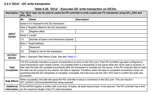
    - I read/write charger registers with I2Cr & I2Cw. With I2Cw I experienced a deviation from manual. If I want to send 0xdc to register 0x17 of the charger from manual I would place 0x6B 0x01 0x00 0x17 0xDC into the TPS data register. Doing so I see the TPS sending 0x6B(W) 0x00 17. I think length must be only one byte and register offset is included in payload. By putting 0x6B 0x02 0x17 0xDC into TPS data register I managed to save 0xdc into register 0x17. The I2Cw command always ACK even when no I2C message is leaving TPS.

    When usb-c is plugged I see the TPS sending periodically

    0x6B(W) 0x19 21.
    0x6B(W) 0x33
    0x6B(R) 0x0E 1B

    Regards,

    Tobias

  • Hi Tobias,

    The initial read should be fine. If the writes look similar, then you should be good, and the image seems to be loading properly.

    - I read/write charger registers with I2Cr & I2Cw. With I2Cw I experienced a deviation from manual. If I want to send 0xdc to register 0x17 of the charger from manual I would place 0x6B 0x01 0x00 0x17 0xDC into the TPS data register. Doing so I see the TPS sending 0x6B(W) 0x00 17. I think length must be only one byte and register offset is included in payload. By putting 0x6B 0x02 0x17 0xDC into TPS data register I managed to save 0xdc into register 0x17. The I2Cw command always ACK even when no I2C message is leaving TPS.

    Yes, you are correct here, there is a typo in the TRM we are working on fixing. See below for the correct formatting.

    When usb-c is plugged I see the TPS sending periodically

    This is fine, on unplug, some "safe config" writes are sent to put the BQ into a known state for the next reconnect.

    Are there any open questions on this thread? Let me know if I missed anything or if you have any other questions.

    Thanks and Regards,

    Chris

  • Hi Chris,

    our  PD+Charger+BMS system still do not charge our batteries.

    I just looked at VBUS when I plug-in usb-c. It stays 0V.

    We are wondering right now if we need PP_5V to power CCx pins?

    In our understanding VBUS powers everything when usb-c is connected so that the tps can configure the power supply. Are we wrong?

    Regards,

    Tobias

  • Hi Chris

    TPS is running smoothly now. It has the right configuration and Charger is configured by it as well. We found a bug in our electronics that prevents the VBUS working correctly.

    We can not charge our batteries still, but I think I will make a new thread in BQ25756 forum because TPS seems to be working fine now.

    Thank you so much for your help!

    Tobias