This thread has been locked.

If you have a related question, please click the "Ask a related question" button in the top right corner. The newly created question will be automatically linked to this question.

LMR51420: The new design issue for LMR51420

Part Number: LMR51420

Tool/software:

Hi,

We use the LMR51420 for the buck design for the input voltage 12-24V, and output is 6.6V, and now we have below issue for this design:

1. We connect the VCC_IN(24VDC) and GND firstly and then turn on the power supply, the output is normal and the waveform as below:

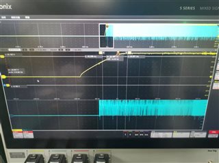
2. We disconnect the VCC_IN and still keep the GND connecting, we turn on the power supply and then connect the VCC_IN to VCC pin, the LMR51420 will be damaged, we measure the device pin and the internal 

highside mosfet and lowside mosfet are both damaged, the power on waveform as below:

3. The below is our schmeatic diagram and we have no idea if there are any error for this design, please kindly review and provide your comment, thanks.

  • Hi,

    I reviewed your schematic. Please confirm which version of the device you are utilizing. If you are using the 500kHz version, the inductor and capacitor combination is appropriately sized. Please also ensure that your capacitors are rated for at least 2x the voltages they are set to experience. 

    In regard to your issue, are you connecting the VCC_IN in the second case to the same point that you are with the first? In that case, you may have an issue where the input transient seen by the device is larger than the absolute maximum as stated in the datasheet section 7.1. This occurs when parasitic inductance (such as due to long wires on input) causes the voltage seen by the VIN pin to ring with a sudden increase in input voltage. To combat this, TI recommends adding a bulk capacitor at the input pin in parallel with the ceramic input capacitors. The ESR from this bulk capacitor will help to effectively dampen any stray inductive ringing that can come from input transient voltages.

    Thank you,

    Joshua Austria

  • Hi, Joshua,

    Thnaks for your reply, we use the full part# is LMR51420YFDDAR and the frequency is 1.1MHz, the LMR51420EVM is based on 500KHz,

    so you mean we need add the bulk capacitor in parallel with the ceramic input capacitors for slow down the rise time of input voltage and 

    dampen any stray inductive ringing; 

    Please kindly suggest what the capacitance value we need to add, still ceramic capacitor or other types of capacitors? thanks.

  • Hi Zhang,

    Ideally, this capacitor would have some ESR to help with this resistance. A simple 22uF or 47uF electrolytic will likely suffice. If you want, you could use a ceramic, but you would then need to add a resistor in series with this capacitor to have a sufficient ESR.

    In terms of value, it may be difficult to determine mathematically as your setup is what will determine your circuit conditions. The EVAL board for this device has a couple electrolytic capacitors listed that should work for your application: https://www.ti.com/lit/ug/sluucg9/sluucg9.pdf?ts=1748474513532&ref_url=https%253A%252F%252Fwww.ti.com%252Ftool%252FLMR51420EVM

    Thank you,

    Joshua Austria