This thread has been locked.

If you have a related question, please click the "Ask a related question" button in the top right corner. The newly created question will be automatically linked to this question.

BQ40Z50-R2: IT Gauging Ext and Load Select default values

Part Number: BQ40Z50-R2

Tool/software:

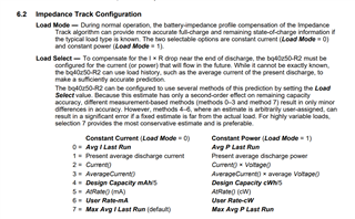
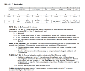
Hi there—our design uses the default values for the IT Gauging Ext and Load Select data flash parameters (0x001A and 7, respectively). Are there any conditions or use-cases for which customers are advised to change either of these parameters from their default values?

We are not experiencing any issues related to gauging at this time; I only ask because we have not given any consideration to these seemingly advanced parameters of the IT algorithm. In case I can provide any additional information, please let me know.

  • Hello Jeff,

    For load select please reference section 6.2 Impedance track configuration for in-depth explanation of load select and selection 15.2.1.11 for IT Gaufing Ext.

    TRM:
    https://www.ti.com/lit/ug/sluubk0b/sluubk0b.pdf?ts=1748444183371&ref_url=https%253A%252F%252Fwww.ti.com%252Fproduct%252FBQ40Z50-R2

    Thank you,
    Alan

  • Hi Alan—thank you for your prompt support!

    I did see these sections in the TRM, but they don't answer these questions. There isn't enough detail here to inform a self-service decision—for example, I don't have any context as to what is meant by the thermal model referred to by THERM_SAT and THERM_IV.

    Similarly, the TRM is clear as to what the different Load Select options represent—but I have no way of knowing what works best for a given application. From my naive perspective, these seem like very advanced parameters of the IT algorithm that are likely tailored to very specific scenarios under the guidance of TI.

    What we're ultimately looking for is some guidance as to how to determine the optimal value for both of these fields (or whether we need to at all). Stated another way—are the default values "one size fits most"? What kind of applications call for these fields to be adjusted, and how would a sub-optimal configuration manifest itself?

    Thanks again for your help—in case I can clarify any of my questions, please let me know.

  • Hello Jeff,

    In terms of Load select I've attached the following scenarios for each selection 

    0 = Avg I Last Run --> For highly variable loads, where there is no prior information about the variability of the load, load select is less conservative than load select 7

    1 = Present average discharge current -->  If the load is variable, but does not have much change through the discharge cycle

    2 = Current() --> For pulsed loads with pulses that are shorter than 10 seconds

    3 = AverageCurrent() --> If the load is variable, but does not have much change through the discharge cycle

    4 = Design Capacity mAh/5 -->  If the load is fixed current or power and has a discharge close to C/5 rate

    5 = AtRate() (mA) --> For highly variable loads, where there is prior information about the variability of the load

    6 = User Rate-mA --> Allows user to select the max expected current and is suitable for pulse loads

    7 = Max Avg I Last Run (default) --> For highly variable loads, where there is no prior information about the variability of the load, Load select 7 is the most conservative option

    *Pulse loads will need testing for different pulse loads in order to obtain the highest SOC% accuracy 

    As for IT Gauging Ext the TRM has the most in-depth explanation but THERM_SAT enable essentially means that it would take in more measurements at the end of the voltage curve and THERM_IV will essentially does the same but in colder temperatures. One thing to note is that enabling all these parameter does add more complexity to the system.

    Thank you,
    Alan

  • Hi Alan—thank you for the update! I am aligned with you about Load Select—in our application, a conservative estimate is preferred; therefore, the default value (7) seems like the best selection.

    Please forgive me, but I am still a bit lost as to whether we need to reconsider IT Gauging Ext. The TRM does mention the existence of a thermal model, but there is little detail as to how it works.

    For example—it seems that if THERM_SAT = 1, the thermal model assumes the simulation temperature is equal to the pack temperature. What does the thermal model ultimately do, and what temperature is assumed instead if THERM_SAT = 0?

    My very naive assumption is that for seemingly advanced parameters like those of IT Gauging Ext, we should leave them set as default unless a problem arises (i.e., do not fix what is not broken).

    What do you typically recommend customers set IT Gauging Ext as? Stated another way, are there any scenarios or applications in which you recommend customers to change this value from the default (0x1A)?

  • Hello Jeff,

    Your update has been received and we are working on your response.

    Thank you,
    Alan

  • Hi Jeff,

    I am aligned with you about Load Select—in our application, a conservative estimate is preferred; therefore, the default value (7) seems like the best selection.

    Regarding the Load Select, would it be possible to receive more information about the discharging load (or types of loads) that will be used in the application, such as whether it will be the same load each discharge, how much it will change, etc? This could give us a better idea of how to go about this parameter. More information regarding the different Load Select values can be found in Section 2.2 of the document below:

    https://www.ti.com/lit/an/slua948/slua948.pdf?ts=1749499882839 

    Please forgive me, but I am still a bit lost as to whether we need to reconsider IT Gauging Ext. The TRM does mention the existence of a thermal model, but there is little detail as to how it works.

    For example—it seems that if THERM_SAT = 1, the thermal model assumes the simulation temperature is equal to the pack temperature. What does the thermal model ultimately do, and what temperature is assumed instead if THERM_SAT = 0?

    My very naive assumption is that for seemingly advanced parameters like those of IT Gauging Ext, we should leave them set as default unless a problem arises (i.e., do not fix what is not broken).

    What do you typically recommend customers set IT Gauging Ext as? Stated another way, are there any scenarios or applications in which you recommend customers to change this value from the default (0x1A)?

    You are correct here, typically we recommend to leave these values as their defaults unless a situation arises where they need to be changed. For some of them, they can be used to tailor other things, such as the [TS1] [TS0] bits, which allow the user to chose what the readout is from the temperature sensors.

    Regarding the thermal model, unless there are some very abnormal temperature situations occurring, I believe these can be left as default. The IT Algorithm will use the parameters Temp A and Temp K for thermal modeling in simulations, where enabling [THERM_SAT] will have the gauge rely on the measured temperature instead of the thermal model for saturation cases.

    If there are questions regarding individual bits in IT Gauging Ext please let us know, however if the performance of the gauge is acceptable currently I believe these can be left as default.

    Regards,

    Anthony 

  • Hi Anthony—thank you for the update, and for sharing this comprehensive application note. In response to your feedback:

    If there are questions regarding individual bits in IT Gauging Ext please let us know, however if the performance of the gauge is acceptable currently I believe these can be left as default.

    I am aligned with you here; we will preserve the default value of IT Gauging Ext.

    Regarding the Load Select, would it be possible to receive more information about the discharging load (or types of loads) that will be used in the application, such as whether it will be the same load each discharge, how much it will change, etc?

    Sure thing—the battery is quite large (C = 25200 mAh) such that the runtime can be many months. The system spends the majority of each day in standby, during which the load current is between 5 mA (0.0002C) and 150 mA (0.006C) as a function of environmental conditions (namely ambient light).

    The system wakes up between one and six times per day at a periodic rate (i.e. every 24 or 4 hours, respectively). During this time, the system draws an average of roughly 275 mA (0.01C) for approximately 90 seconds. There may brief periods of inrush (e.g. 0.1C), but these generally last less than 1 ms.

    The user can also manually wake up the system in between these 4–24 hour standby periods, but this is likely to be infrequent throughout the months-long runtime. For example, the user may manually wake up the system several times within one hour, then defer to automatic wake-up throughout the next several days or more.

    As the load is somewhat variable, and a more conservative approach is preferred, my naive understanding is that the default value (Max Avg I Last Run = 7) as described in the TRM seems most appropriate. However, this is only my uneducated guess; please let me know in case you disagree.

    One related question—the application note refers to the default value using different language (Present average load from the beginning of the current discharge cycle)—is it the same idea?

    Please let me know whether this information is helpful in selecting the appropriate value for Load Select, or whether I can provide any additional details about our application. Thanks again!

  • Hello Jeff,

    Your update has been received and we are working on your response.

    Thank you,
    Alan