Other Parts Discussed in Thread: TPS26750,
Tool/software:
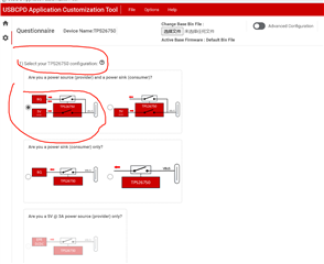
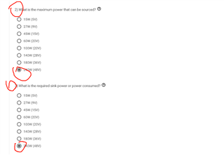
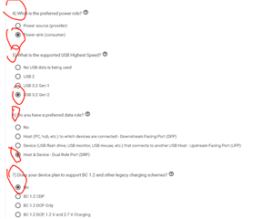
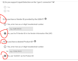
We are developing a 240W charging and discharging point using the TPS26750+BJ25756 solution, with a type-c interface and Horizon as the main controller. We will use PCIe to extend USB 3.0 and connect TYPE-C for communication. At the same time, we need to charge the internal battery, which has 11 strings and is approximately 46.2V. We also need to support 240W discharging, which is based on the PD protocol. We need to understand the configuration issues.
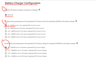
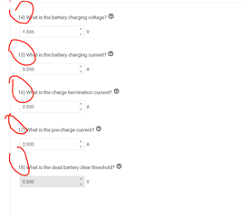
1. Is the current configuration as shown in the picture reasonable?
2. What is the default setting when EEPROM is not burned?
3. At present, it can be charged, but the output can only be given to one device; Is there any way?
4. Do you have any files for the configuration of PD for us?