This thread has been locked.

If you have a related question, please click the "Ask a related question" button in the top right corner. The newly created question will be automatically linked to this question.

BQ40Z80: Connection issue of the VSS pin to the negative terminal of the battery pack

Part Number: BQ40Z80


Tool/software:

 Hello,
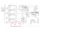
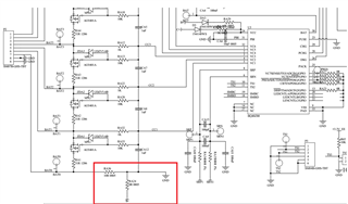
I inquired about the connection between the VSS pin and the negative pole of the battery pack in the BQ40Z80, is there a big problem with the connection in the attached picture, such as the current jump problem?

  • Hello FeF.

    The components highlighted in the red box aren't reflected in the example schematics provided by TI for external cell balancing, however what are you referring to "current jump"? Are you referring to a jump in the load from the current, arching being the components happening and etc. 

    Thank you,
    Alan

  • Hello, Alan
    M
    y problem is the design review of the VSS pin connection for BQ40Z80; First of all, because our load current is very large, the negative electrode (BAT0) sampled by cell 1 and the total negative electrode (B-) of the battery pack are separated paths, and GND is connected to the VSS pin of the BQ40Z80; In this way, we want to avoid VC1 voltage sampling offset when the load is high-current;
    1. GND is connected to the negative pole BAT0 of cell 1 through RA36=10R resistance;
    2. GND passes the RA24=0R resistance to connect the total negative pole of the battery pack B-;
    At present, I know that this design is not helpful for VC1 voltage sampling, and theoretically RA36 and R24 can switch positions to meet the stability of VC1 sampling;
    I'd like to know if there is any impact on current sampling (e.g. sudden current changes and reverse currents) or other issues if the connection is as it is now;

    Thank you for your help;

  • Hello Fef.wan,

    Could you send your entire schematic of your battery gauge since for the following reason below 

    1. GND is connected to the negative pole BAT0 of cell 1 through RA36=10R resistance;

    -Adding a 10R resistor would create heat since the current is pasting through the component

    . GND passes the RA24=0R resistance to connect the total negative pole of the battery pack B-;

    -There should be a sense resistor in-between the pack - and the battery - to measure current 

    Thank you,
    Alan

  • Hello, Alan
    1
    . I will send the complete schematic diagram to you for review and confirmation, see the attachment;
    2. Our project is mainly for large load applications, so we want to separate the power wires of VSS and B- to reduce the sampling effect of VC1;

    Thank you for your helpBQ40Z80-.PDF

  • Hello FeF.wan,

    Due to workload we are asking more time to work through e2e.

    Thank you,
    Alan