This thread has been locked.

If you have a related question, please click the "Ask a related question" button in the top right corner. The newly created question will be automatically linked to this question.

TPS23758: Ground connection considerations, VSS, PGND, GND, Earth

Part Number: TPS23758

Tool/software:

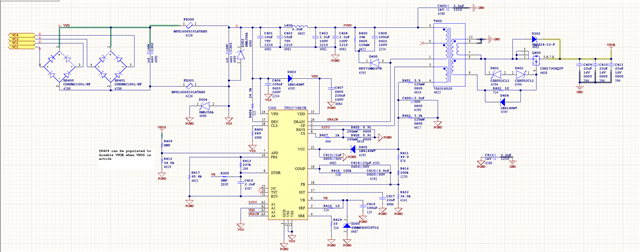
I had a previous open ticket regarding my TPS23758 design and at the end of the conversation potential handshaking issues as a result of grounding were brought up.  I am seeing an issue resurfacing of failed POE circuits on some fielded units and I don't have a good sense of what the field conditions were that lead to failure. 

I would like to understand the TI engineer's comment about potentially shorting the various ground rails to Earth and what that might cause in terms of issues.  The specific comment from that thread was:

"Another factor could cause handshake failure is the grounding connection: for example have you shorted VSS, PGND, or GND to earth?"

Thank you,

Matt

  • Posting my grounding for the system.

  • Hi Matt,

    Thanks for your follow-ups. I found our old conversation via:

    https://e2e.ti.com/support/power-management-group/power-management/f/power-management-forum/1290735/tps23758-weak-points-in-design-leading-to-failure/4896498?tisearch=e2e-sitesearch&keymatch=%2520user%253A583396#4896498

    Looks like the GND connections are correct. The EGND is decoupled with VSS and RTN

    You mentioned the DC/DC can work well when you use adapter and APD pin. This could be PoE's issue due to detection/classification. It could also be the PSE disconnect the PD since the PD draw too less current from the PSE. The PSE need a minimum maintain power signature current form PD.

    - Could you show a waveforms of VDD-VSS at the failed board? In a time window of 1-5s with100ms/div or 500ms/div?

    - Could you try to test the failed board with full load 3.5W set at turning on (maintain power signature may needs PD has >14mA DC current) ?

    Best regards, 

    Diang

  • Hi Diang,

    Thank you for your response! 

    To clarify my comment from the other thread, my system has two potential sources for 5V DC.  One from a USB supply (VBUS) and one from the POE circuit (VPOE).  If I power up the system via VBUS, the load works and performs as expected, regardless of whether VPOE is generated correctly.  On a "bad" board I can power up VBUS and still observe the same issues with the POE circuit.  Ensuring the load is there does not appear to help achieve a stable VPOE rail unfortunately.  I tried turning on the load with VBUS, providing POE power and then disabling VBUS to see if VPOE could stabilize but it would not.

    APD is also pulled low and not connected to VBUS currently.

    Here is VDD to VSS with 100ms/div.  Its a pretty stable 55V DC.  The 500ms scale looks the same.

    I've also scoped some of the other signals on a "bad" board, here is DRAIN to PGND:

    CP to PGND:

    fVPD to PGND (the output of the rectifier):

    VCC to PGND:

    Thank you for the help,

    Matt

  • Hi Matt,

    Thanks for your waveform. Looks like it is not a handshake issue since we can see there are some switching waveform even on the bad board. It may be an issue of the DC/DC: 

    The SRF resistor (R426) is only 10-Ohm, which is low for TPS23758's integrated MOSFET. The 2nd side sync FET (Q400) and Zener diode (D302) are either 30V or 24V. No snubber RC to reduce Q400's overshoot. When switching speed is fast as R426 is only 10-Ohm, there could be higher overshoot at Q400 and D302, which could cause Zener diode avalanche every switching cycle and degraded fast.

    You may try below actions on bad board:

    1. Try to replace Q400 with new FET, better with 40V voltage rating

    2. Try to replace D302 with a new Zener. If FET is 30V, you can keep the 24V Zener; If FET is 40V, Zener is 32-36V.

    3. Use R426 = 50 Ohm

    4. Power on the bad board again to see if it can recover.

    Best regards,

    Diang

  • Hi Diang,

    Great suggestion, I replaced R426 with 50 ohms and it didn't recover the boards, but I started looking at D302 and Q400 and it looks like Q400 could be damaged from the exact scenario you outlined.  I have some new higher voltage parts on order to try.

    Do you recommend adding a snubber RC to reduce Q400 overshoot?  Are R10 and C18 from the eval kit is an example of what you're referring to?

    I will report back, thank you!

    -Matt

  • HI Matt,

    Thanks for your reply.

    Yes snubber RC is recommended and you can use the EVM values as the initial values to test. 

    Waiting for your test with new FET / diode.

    Best regards,

    Diang

  • Hi Diang,

    Replacing Q400 with a new FET recovered the bad board, so it was indeed the FET being damaged. 

    Can you help me understand what the mechanism of failure is and how I might be able to observe the problem (overshoot?) on a board and then what to look for on an updated board (with slower SRF, snubber and high voltage components) to confirm the issue is resolved.  Am I looking for voltage spikes across Drain-Source on Q400 that are higher than the part is rated?

    Best Regards,

    Matt

  • Hi Matt,

    Q400 is the sync FET on the flyback secondary side. When primary FET inside TPS23758 turns on, and Q400 turns off, the Q400's Vds(off) could be Vout + Vin/Npri*Nsec + overshoot. The overall values could exceed the 30V rating. Overshoot mainly comes from transformer leakage inductance and stray inductance.  Adding series RC snubber can help to reduce the overshoot: smaller R + higher C for smaller overshoot but higher switching loss as a trade off. You can start with the EVM values to test.

    Best regards,

    Diang 

  • Hi Diang,

    Got it, thank you.  I was able to scope Vds for three configurations: no snubber, EVM snubber and 2.6 ohm EVM snubber.  I like the look of the 2.6 ohm snubber circuit because it reduces the overshoot by 6 volts and that in conjunction with a higher voltage MOSFET should be much more resilient.

    I will be changing to a 60V MOSFET and a 51V Zener with a 50 ohm SRF.

    Thank you for the help!

    -Matt