This thread has been locked.

If you have a related question, please click the "Ask a related question" button in the top right corner. The newly created question will be automatically linked to this question.

UC2846: uc2846

Part Number: UC2846
Other Parts Discussed in Thread: TL431

Tool/software:

Hi,

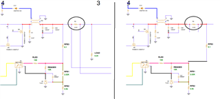
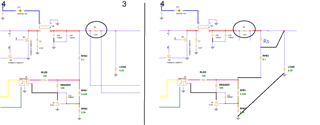
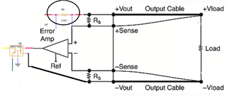
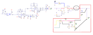
we are using ic UC2846 for designing dc to dc converter & we want to add feature like remote sensing & trimming with this ic kindly suggest the circuit for remote sensing & trimming function.

Thanks,

Rohit Gupta

  • Hi,

    What do you want sense remotely and how far do you mean in terms of remote between sensing variable and the uc2846?

  • I want remote sense the voltage at the load and regulate it automatically to the desired value 

  • Hi,

    Can you please provide your circuit without remote sense to me so I can suggest how to change or add circuit to do remote load voltage sense?

  • UC2846.pdf

    Here the pdf file of schematic

  • Hi,

    I see you have an output load current sense - you need to move this sense to the left of load voltage sense.

    A simple remote sense is like the below:

    You need to insert Rs (typically 20ohm to 100ohm - you need to use trial and error to decide). Then two sense lines in black which cannot share the output current traces and wires so the two black sense lines have no voltage drop virtually.


    More effective remote sense needs to add in differential amplifier to replace your TL431 circuit control circuit. The below shows an overall idea. Error Amp needs to add feedback divider and loop compensation - these are not showing.

  • plz provide us the reference ckt with OP-AMP for Voltage sense and Trim functions. you can choose half bridge or push pull topology

  • Hi,

    We do not have a reference circuit in half bridge or push pull. The below is what I have. You can draw this into your circuit and send back to me for review.

  • There are two circuits used for remote voltage sensing: one is op-amp-based, and the other uses a simple potential divider. In the op-amp-based circuit, I noticed that the load ground is connected to the remote sensing ground through a 100 Ω resistor. However, in the potential divider circuit, the load ground and the sensing ground are directly connected (shorted) without any resistor.

    I’d like to know which of these grounding methods is correct for proper remote sensing. Additionally, we are looking for a circuit that includes a trimmer adjustment function.

  • Hi,

    If you use a differential amplifier then you sense the load voltage differentially so ok to connect 100-ohm. If you do not use a differential amplifier, connecting 100-ohm may not provide any benefit to you but it is ok to connect and you can test to see if any benefit. If no benefit then you can save one component and some board space by not connecting the 100-ohm.

  • Hi,

    Could you please provide the equations for calculating the resistor and capacitor values for both scenarios?

    Thanks,

    Rohit Gupta

  • Hi,

    Resistors and capacitors are part of your regular converter design. If you need to get a custom design, please contact your TI sales office.

    Please design your converter first without remote, then add remote sense. For differential amplifier remote sense, you need to review the differential amplifier design. Differential amplifier as an amplifier design is straight forward and can be found in college electronic textbook.