This thread has been locked.

If you have a related question, please click the "Ask a related question" button in the top right corner. The newly created question will be automatically linked to this question.

TPS274C65: Fault signal drops twice at power-on time and the output oscillates at the switching time after power-on.

Part Number: TPS274C65


Tool/software:

Hi Ti experts,

My customer uses TPS274C65AS in PLC IO module. They met some issues and have five questions:

Q1: After power-on, 0h register is 0x81 or 0xC1, which means there is a UVLO case. Is it normal. Is there a actual UVLO case.

       What operations should customer do on registers after POR. Customer didn't use NMOS for RCB. I know customer should set 23h bit7 RCB_DIS to 1. Anything alse?

Q2: After power-on, 0x register's value is not same as customer's expectation. Customer read once all the registers and 0h register back to 0x00. Is the reason that 2h register's type is RC and it will reset 0h register after once read operation.

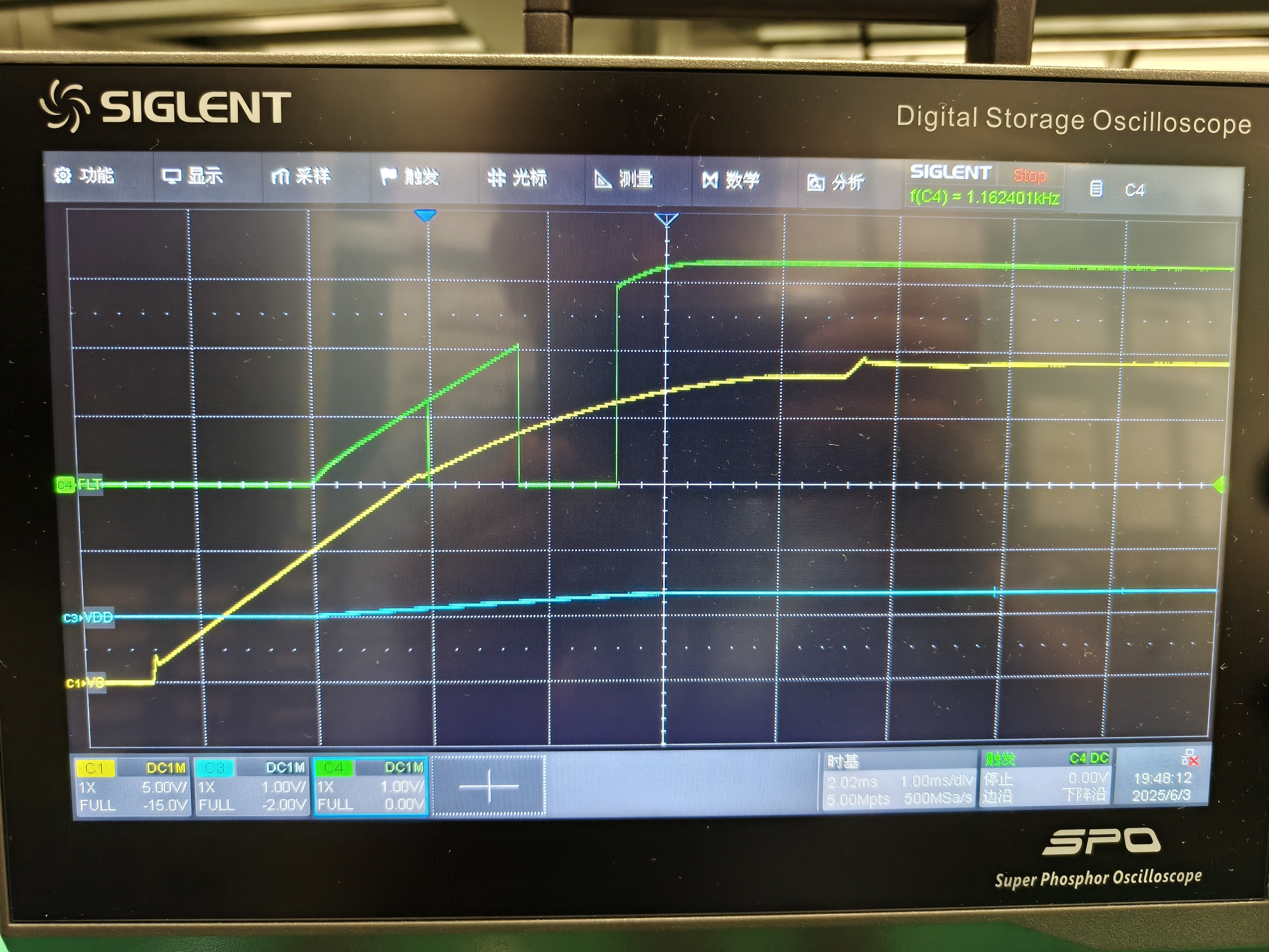
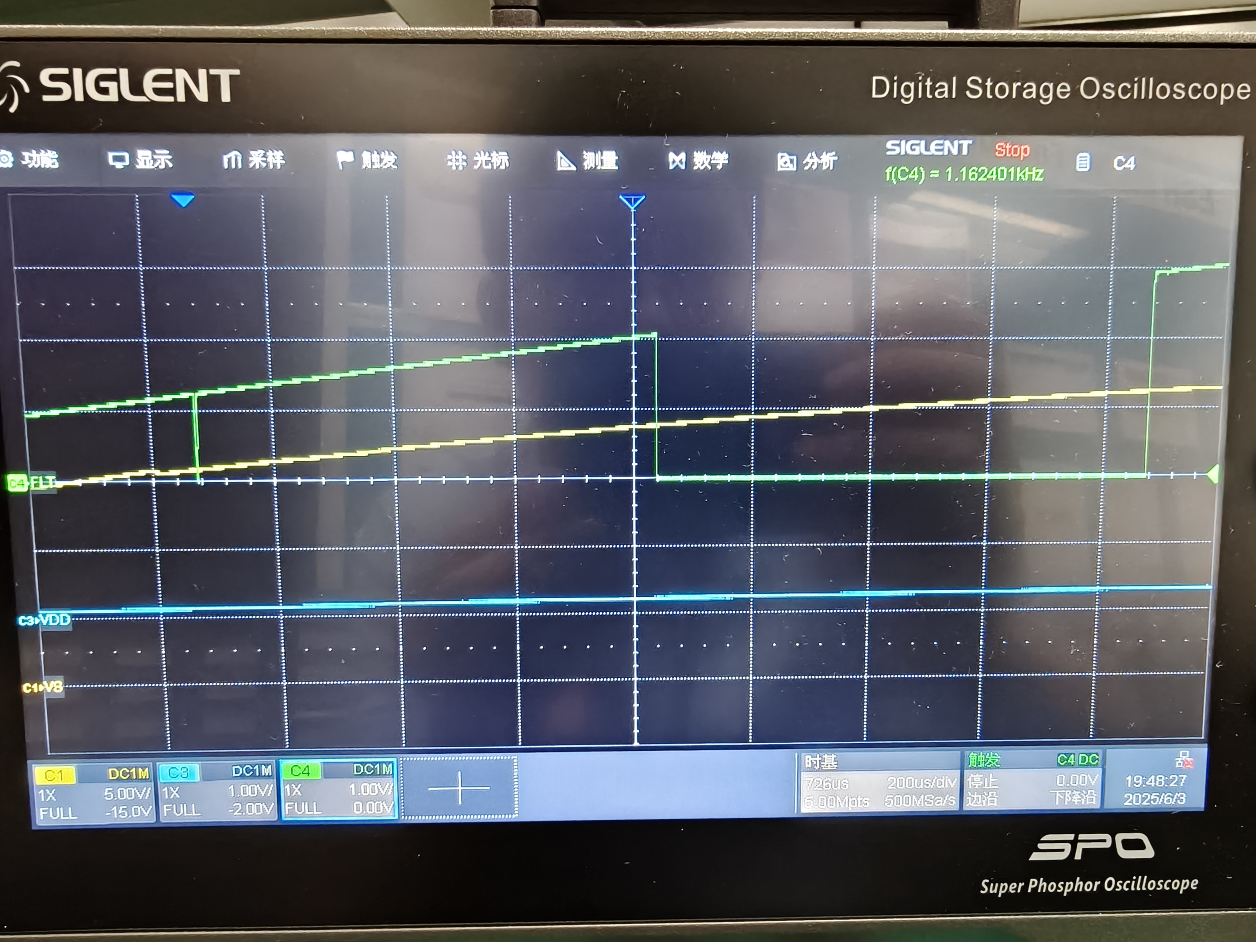
Q3: Fault signal will have twice drops when POR. Is it normal?

Yellow is Fault signal and green is VDD from IC internal LDO rather than external DCDC.

Q4: Output voltage, input voltage and fault will have output oscillations when normally working. This is a mandatory malfunction. 


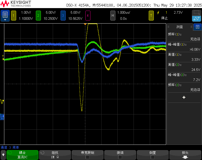
Yellow is fault. Blue is VS. Green is output. You can see each time when the ouput opens, there will be a oscillation.

Q5: After POR, Customer only operates 1Dh register. Fault will have a drop sometimes but output voltage will not drop at the same time. But after customer read once all the registers. The issue will not happen.

Yellow is fault signal(Green is on the MCU side after optical coupler). Red signal is the output voltage. Blue signal is the 

You can see output voltage didn't drop though fault drops.

  • Hi Gary,

    1. Yes, this is normal for the first read upon powerup because the UVLO is latched. If they read register 0 again, they should see the MSB be 0.

    Otherwise, the customer should configure the device according to the features and thresholds they require.

    2. Yes, that's correct. The default register value for each register is written above each register description.

    3. Yes, this is normal.

    4. Does this happen every time the channel is enabled? The supply droops when this happens. Do you have a waveform of the current during this behavior? And, if the switch is bypassed, does this still happen when the load is connected?

    5. The fault pin can go low due to a fault that does not disable the channel, for example VS_UV_WRN. When they see the fault pin go low and read the fault registers, what faults do they see?

    Thanks,

    Patrick

  • Hi Patrick,

    Thanks for your reply. Quite helpful.

    Now customer fixed all other questions except Q3, which is that there will be two drops of FLT when POR. could you explain what are these FLT. Both are UVLO? 

    I tested TI EVM: TPS274C65USBEVM and it originally use onboard BUCK to generate VDD.

    Below are the results.It alse has two drops of FLT.

     \

    What the results if I use internal LDO for VDD. Two drops of FLT will disappear?

  • Hi Gary,

    I'm not sure yet what the first FLT assertion is, but the two assertions align with VS_UVLO_WRN and VDD_UVLO, respectively, as you mentioned. Are these FLT assertions an issue for the customer?

    Thanks,

    Patrick