A related question is a question created from another question. When the related question is created, it will be automatically linked to the original question.
If you have a related question, please click the "Ask a related question" button in the top right corner. The newly created question will be automatically linked to this question.
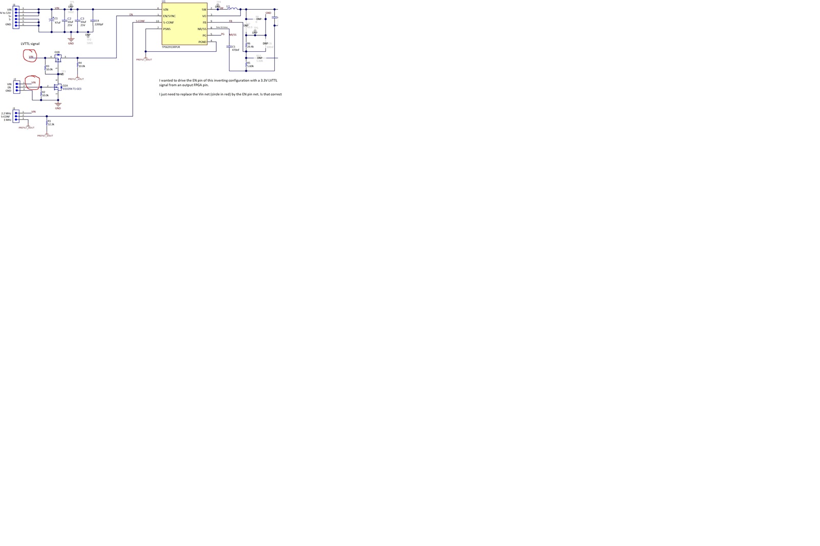
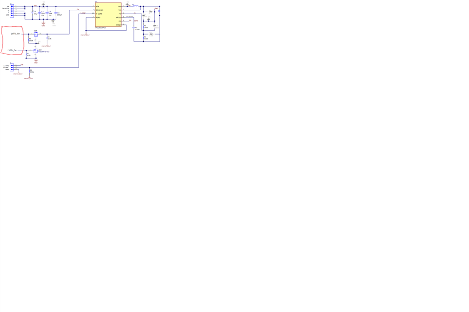
The microcontroller output is a positive signal while Vout is a negative 3.3V. I thought we will need the Q1 and Q1A to translate as the volatge translator? Correct me if I am wrong, i might have interpreted section 1.2.2 incorrectly.
In the intialisation of the microcontroller, the EN pin will be in tri state (high impedance state ). Will the tps62913 be turned off when the enable pin is in the high impedance state? I want the tps62913 to be off when the enable pin is the tri state mode.
The microcontroller output is a positive signal while Vout is a negative 3.3V. I thought we will need the Q1 and Q1A to translate as the volatge translator? Correct me if I am wrong, i might have interpreted section 1.2.2 incorrectly.
You're right. Q1 & Q1A will do so. I somehow missed the inverting fact while suggesting direct GPIO connection.
In the intialisation of the microcontroller, the EN pin will be in tri state (high impedance state ). Will the tps62913 be turned off when the enable pin is in the high impedance state? I want the tps62913 to be off when the enable pin is the tri state mode.
EN internally has pulldown resistor of 500kE. So, at MCU init stage EN will be disabled.