This thread has been locked.

If you have a related question, please click the "Ask a related question" button in the top right corner. The newly created question will be automatically linked to this question.

TPS63802: Measuring negative current at output

Part Number: TPS63802

Tool/software:

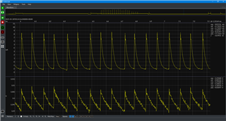
Hi, I am using the TPS63802 to supply 3.3V to a Wi-Fi module. When the Wi-Fi module is in a low power mode, it consumes very little in the order of tens of microamps. When measuring this with an energy analyser however (JS220), I notice I get different results if I use the TPS63802 to supply it, compared to a lab bench power supply. Debugging this further, I measured negative current spikes when using the TPS63802 which I believe correspond to the regulator switching.

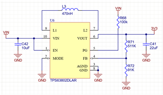
I also get the same results using the TPS63802EVM, so I am confident my layout and components chosen are not the cause, but this is my schematic to show how it is configured when I see these spikes.

I believe it is something to do with PFM mode, as when I change MODE to high when using the TPS63802EVM the spikes go away and I measure the same power consumption of the Wi-Fi module as when I use a lab bench power supply. My suspicion is the energy stored in the inductor and output capacitor is too much, and there is too little load to absorb the excess energy which causes it to momentarily flow back into the regulator. Does this sound plausible, and is this expected to begin with? I also see the negative spikes increase to become even more negative if the load is increased.

Any extra information to explain why this happens would be much appreciated. Please let me know if you need more information from my end.

  • Hello Jonathan,

    Where do you measure with the energy analyzer?

    Best regards,
    Brigitte

  • Hi Brigitte, I measure at the output of the regulator. The net "3V3" in the schematic above connects to a jumper which then supplies the Wi-Fi module. This jumper is removed, and the energy analyser is placed across this.

    Thanks,
    Jonathan

  • Hi  Jonathan,

    From my understanding ,  load characters of  power analysis should close to electronic load, a capacitance load with low bandwidth.

    Then, it is not able to response the frequency of vout ripple in PFM mode, which means it will cause an instable Iout as you observed. Once you change your operation mode to FPWM. The vout ripple gone, i mean compared with ripple PFM mode, it is small enough to ignore. 

    Also,  A lc oscillation may exist between your output cap, output cable and power analysis, then a negative current is makes sense too. 

    I think it is a normal behavior but not issue.

    Regards

    Tao

  • Thanks Tao for your reply. Can I please clarify your response. Are you saying the measurement system (the Joulescope in this case), is acting as a capacitive load with limited bandwidth? And this load is unable to respond to the vout ripple in PFM mode? Could you please expand on this part? I am unclear how this causes an unstable Iout. Are you saying the Vout ripple is to fast for the Joulescope to capture properly?

    Thanks,
    Jonathan

  • Hi  Jonathan,

    Yes, your understanding is correct, when the bandwidth of energy analyser is very low, it is not able to adjust the actual load to respond. I think you can treat the energy analyser as a constant resister load which means the Iout will change with Vout.

    Regards

    Tao

  • Thanks again Tao. So does this mean the negative current I am seeing is real then? Or simply an artifact from my measurement setup?

    It sounds like my initial hypoethesis was not correct then either, do you agree this is not the case?
    "My suspicion is the energy stored in the inductor and output capacitor is too much, and there is too little load to absorb the excess energy which causes it to momentarily flow back into the regulator."

    Kind regards,
    Jonathan

  • Hi  Jonathan,

    For negative, both suspicion from your side is possible. it is just a LC oscilaltion, may cause a negative current, also, may caused by measurement set-up.

    In you initial suspicion, what do you mean the inductor, power inductor of converter or parasitic inductor of the output cable?

    For a LC system, once there is status change for either L or C, oscillation triggered.

    Regards

    Tao

  • Hi Tao,

    I was referring to the 470nH power inductor.

    Do you have a recommended method to test if an LC oscillation occurs?

    Kind regards,
    Jonathan

  • Hi  Jonathan,

    May me you can try a comparison test with a different output cable, or add an additional inductor between output cap and energy analyser.

    Regards

    Tao