This thread has been locked.

If you have a related question, please click the "Ask a related question" button in the top right corner. The newly created question will be automatically linked to this question.

LM60430-Q1: Output Capacitor

Part Number: LM60430-Q1
Other Parts Discussed in Thread: LP87524J-Q1

Tool/software:

Hello,

I have a question regarding the output capacitor configuration for the LM60430-Q1.

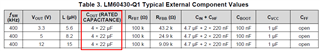
According to the datasheet, the recommended output capacitor configuration consists of four 22uF capacitors. We understand that this recommendation is intended to ensure stable operation under the maximum load current of 3A.

In our application, however, the maximum current required from the LM60430-Q1 is only around 720mA to 1A. Therefore, we are considering reducing the output capacitance to two 22uF capacitors.

Could you please confirm whether this configuration would still be acceptable for our lower current requirement? We would appreciate your guidance on this.

Thank you.

  • Hi Donghyun,

    Thanks for reaching out!

    You can try simulating the device on WEBENCH and change the passives based on what you plan on using and your operating conditions.

    The values recommended in the table are only typical and the device can operate with different passive combinations based on the output voltage, input voltage range, transient requirements (load and line), etc. 

    Any reason why you are using a 3A rated device for an application that only requires 1A of current?

    Thanks,

    Best Regards,

    Taru

  • Currently, due to a request from our customer, we need to obtain confirmation from TI regarding our output capacitor configuration.

    In our application, the input voltage range for the LM60430-Q1 is 9–16V, and the output voltage is 5V. This 5V output is used as the input voltage for TI’s PMIC LP87524J-Q1. As mentioned previously, the maximum load current is 720mA.

    Given these conditions, we would like to request confirmation on whether using two 22uF output capacitors for the LM60430-Q1 would be acceptable without any issues.

    Thank you for your support.

  • Hi Donghyun,

    As mentioned to you WEBENCH should tell you. Please see the simulation here: https://webench.ti.com/appinfo/webench/scripts/SDP.cgi?ID=6A1EB4FB983D2213

    With 22uFx2 - the phase margin of the design is too low.

    Having said that - there are much better devices suited for this application. Please see https://www.ti.com/product/LMR60410 - this device can work with much lower output capacitance. 

    Hope this helps.

    Thanks,
    Best Regards,
    Taru

  • Hello,

    We are currently using the LM60430-Q1 in our design, and there are specific reasons why we are strongly committed to this device.

    The EMI performance of the LM60430-Q1 is excellent, and its low dropout voltage is highly beneficial for our application. Most importantly, we have already passed EMC testing with this regulator, so switching to a different device would require significant design changes and retesting, which is not a trivial decision for us.

    Given this context, we would like to ask for your support in confirming a key design parameter:

    Under the following conditions:

    • Input voltage: 9–16 V

    • Output voltage: 5 V

    • Maximum load current: 750 mA

    • Maximum allowable output voltage deviation (ΔVOUT): 300 mV

    Could you please confirm the minimum required output capacitance to ensure stable operation and acceptable transient response?

    We are trying to minimize the output capacitor value because our PCB space is very limited.

    We would really appreciate your help in confirming this value so that we can evaluate whether any further design trade-offs or regulator changes are necessary.

    Thank you very much for your support.

    Best regards

  • Hi Donghyun,

    WEBENCH recommends derated output capacitance of around 85uF (Capacitance degrades as the DC voltage rises). You can use 2x 100uF caps (or 3x 47uF) at the output like here: https://webench.ti.com/appinfo/webench/scripts/SDP.cgi?ID=8192F5C56710A067. This should save you space. 

    You can play around with options in WEBENCH to understand what best works for you. WEBENCH also lets you customize your design for small footprint. 

    Hope this helps. 

    Thanks,

    Best Regards,

    Taru

  • Hello,

    The output of this regulator is used as the input to a PMIC (LP87524J), and there are four 10uF capacitors connected in parallel at the PMIC input.
    Would it be possible for these PMIC input capacitors to compensate for the insufficient output capacitance of the LM60430-Q1?

    If layout distance is a critical factor, could you advise how close the regulator output and the PMIC input should be placed (in millimeters)?

    Looking forward to your response.
    Thank you.

  • Hi Donghyun,

    Apologies for the delay - I was out of office for the past week or so. 

    if I understand correctly, 

    You are asking if the Buck and PMIC in the above picture are close enough - can you consider the input cap of the PMIC as part of the output capacitance of the buck? Right? 

    Thanks,

    Best Regards,

    Taru

  • Yes, that's correct. I'm asking how close the Buck and the PMIC need to be in order for the input capacitors of the PMIC to be considered as part of the output capacitance of the Buck regulator.

  • Hi Donghyun,

    Theoretically speaking - this can work.

    However, it is very difficult to say if this will work in practice. It depends on your PCB routing and power delivery network - this will require you to model your PCB parasitic inductance and capacitance - which will determine how your transfer function will look like and if the PMIC input capacitance can 'add' to the DC/DC output capacitance. 

    You can check if the load transient response is according to your expectations - If yes, you can go ahead with the current implementation as well. 

    The best way here is to place 2x 100uF as suggested earlier which should take up almost the same amount of space as 2x 22uF. 

    Thanks,

    Best Regards,

    Taru