Tool/software:
We have been working on a high power POE design and have looked at all 3 eval kits for the TPS2373. Each one has a slightly different front end, and each has its own efficiency benefits.
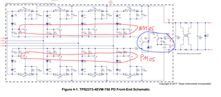
TPS2373-4EVM-758 - discrete full bridge Ideal Diode FET. Best efficiency compared to diode-only bridge.
TPS2372-3EVM-757 - discrete full bridge with Ideal Diode FETs only on low side, high side uses Diodes. Moderate efficiency
TPS2372-4EVM-006 - Uses the bridge ideal diode chip. Moderate efficiency.
We implemented our own stripped-down version of the 4EVM-758 where we don't have BJTs on the gates of all of the FETs. We also built just a "half" version where we weren't concerned about input voltage polarity reversal. Unfortunately, we have some backfeed issues if we have a pre-biased load on the output. It's probably due to our half version, so we understand that.
What we are wondering is when we're modeling our front-end after these circuits, why do the 4EVM-758 and 4EVM-006 use BJTs in the gate drive circuitry rather than FETs?
can we use small signal FETs in place of the various BJTs?
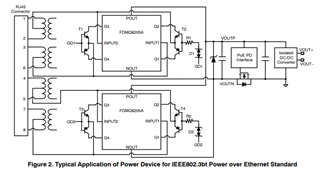
when replacing the bridge w/ the FDMQ8205A, could we just replace the control BJTs w/ FETs?
Thanks