This thread has been locked.

If you have a related question, please click the "Ask a related question" button in the top right corner. The newly created question will be automatically linked to this question.

TPS513885: TPS513885 Not working on 24V

Part Number: TPS513885
Other Parts Discussed in Thread: , TPS51388EVM, TPS51388

Tool/software:


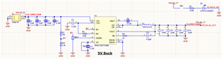
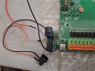
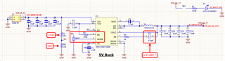
this is the schematic

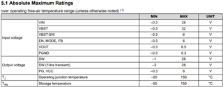
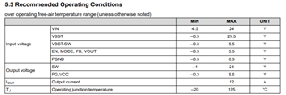
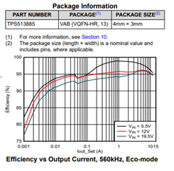
I’m working with the TPS513885VABR buck controller in a design that needs to support input voltages from 5V up to 24V. The circuit works perfectly when VIN is between 5V and 12V, but when I apply 24V at the input, the IC fails to start.


Observed Behavior:

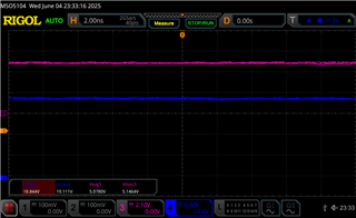
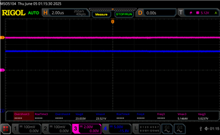
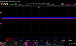
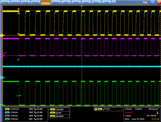
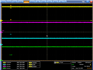
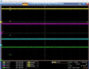
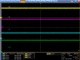
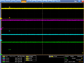
  • VIN = 24V is stable and clean.

  • No switching occurs at the SW node.

  • VOUT remains at 0V.

  • PGOOD stays low.

  • VREG5 and VREG3 do not come up.

  • No signs of overcurrent or thermal damage.

  • EN pin is pulled high and confirmed above the threshold.

  • Input capacitors are 35V rated MLCCs.


What I’ve Tried:

  • Verified that VIN doesn’t dip during startup.

  • Removed the load completely and still no output.

  • Confirmed that the BOOT capacitor is present and correctly rated.

  • Measured BOOT-SW and found it not charging at 24V.

  • Lowering the input to 18V–20V sometimes results in startup, but not consistently.


Questions:

  1. Could this be related to VIN overvoltage protection or internal biasing failure at higher input voltage?

  2. Is there any known issue with VREG5/VREG3 startup at higher VIN?

  3. Are there layout sensitivities at higher input voltages that could prevent the bootstrap circuit from functioning?

  4. Any test points or debug suggestions to check for internal protection triggers?

  • Hello Customer,

    We are checking internally why at 24V input why buck is not switching.

    Mean while can you check below:

    • Directly are you applying 24V at buck input ?
    • Apply 15V at buck input and increase the buck input voltage in steps of 300mV and upto 24V and see at what point the buck will shutdown.

    Regards,

    Haseen.

  • Hello,

    No, we are using 2 adapters one is of 12V and other is of 24V

    when using the 12V adapter it works fine. But as soon as we plug in the 24V adapter the IC stops working and wont work with 12V adapter either. 

  • Hello Parth Parekh,


    You have mentioned that "But as soon as we plug in the 24V adapter the IC stops working and won't work with 12V adapter either" >> after power cycle is the device working again?

    Also, can you share the waveforms of VIN,PG,VCC & SW for both 12V and 24V adapters also the Zoom portion of VIN raising at starting.

    How many devices you have tested and how many are showing this issue?

    Regards,

    Haseen.

  • Hello Parth Parekh,

    Since we didn't hear from you and we think that issue is solved.

    Regards,

    Haseen.

  • Hi Haseen,

    here is the link of DSO testing which include below testing parameters:

    https://drive.google.com/drive/folders/1ojFvlorHyYkdrmNttPktm_d10fjXnySo?usp=sharing

    1. we tested with 12V 0.5A adaptor : working perfectly with and without diode protection

    2. we tested with 12V 3A adaptor : working perfectly with and without diode protection

    3. we tested with 12V 10A adaptor : not sustained without diode protection (not tested with diode protection)

    3. we tested with 24V 2A adaptor : working perfectly with diode but not sustained when removed diode.

    4. we tested with 19.5V 2A adaptor : working perfectly with and without diode protection


    we have blown away 6 or 7 buck converter ICs, all have different fault

    one have showing short between output and gnd 

    one have showing short between input and gnd

    one showing short at both end 

    one showing short between feedback pin and gnd 

    we are not able to understand what is the main reason behind the issue, the datasheet showing it has absolute maximum input voltage capabilities up to 28V and typically 24V.

    we also found out that there is not single graph shown in datasheet which has used input supply of 24V, there is only 3 input supply tested and showed with graph 5.5V, 12V and 19.5V.


    is that mean this IC is not capable to handle 24V as input ?

    our testing conclusion also found whenever input supply voltage touch to 24V or more it blown away and short internally, all components in the circuitry working perfectly accept buck converter.

    Regards,

    Dhruvit

  • Hi Dhruvit Bhimani,

    I don't have access to google drive which you have shared.

    Can you zip the waveforms and share it with me at a1243146@ti.com.

     Also where exactly you are measuring the input voltage (right at the Buck VIN pin or before VIN capacitors? - please share the photo of measuring point.

    Regards,

    Haseen.

  • Hi Dhruvit Bhimani,

    Also what is this means "we tested with 24V 2A adaptor : working perfectly with diode but not sustained when removed diode" - where you have connected the diode in circuit.

    Regards,

    Haseen.

  • Hi Haseen,

    I have mailed all drive files.

    we are measuring voltage before VIN capacitor,

    our power supply is giving 24.1V or 24.2V voltage sometimes, to encounter this we have placed junction diode at input supply so that 0.7V drop make it to 23.5V to 23.6V so the upper maximum 24V limit can be secured.

    we thought these can be issue but our one of device just blown out which is running on 12V 0.5A since last 2 days, few minutes ago when we disconnect the supply and again connected it didn't start, we check it with DMM, and output is same VOUT shorted with GND.

    we are thinking about total wattage it take compare to its output, based on that if output at 5.15V 12A then total output power is 61W, if we divide this with 24V and 12V then 12V 5A and 24V 2.5A can be maximum input supply.

    Video's are compiling in mail.

    here blue is input and Pink is output.

  • Hi please review this 2 video 

    in with diode configuration buck working perfectly 

    when we do same without diode its suddenly blown away.


  • Here is one more instance 

    in 1st image as you can see we have used 24V supply with diode in between so average 23.3 something is going in to Buck converter, in pink side as you can see 5.1V average is coming out of Buck converter.

    in 2nd image, now we have turned off the buck and again turned on, this time it showing unwanted behavior for same input supply it is giving output of 2.3V to 2.5V.

    when i checked enable pin, its 0V which means something happening with this buck with 24V supply.


  • Hi Dhruvit Bhimani,

    From the video i see that you are measuring input voltage using multimeter and it will show average value(we miss instantaneous value).

    However we would like you to capture input voltage right at the buck input pin VIN pin1 in oscilloscope set trigger on VIN at 15V set 50ms/div and it will capture starting voltage and we can see spike is within the limit or not.

    Capture above waveforms with and without diode.

    Once you capture above waveforms as an experiment connect 200uF electrolytic at VIN pin and see the input voltage at starting. 

    Regards, 

    Haseen.

  • Hi Haseen,

    We have tested the setup based on your given instructions at the VIN pin of the buck converter.

    We used a 270µF, 35V electrolytic capacitor along with a 24V power supply.

    Images of both setups have also been shared.


    now used with 270uF 35V electrolytic capacitor at input side.

    I hope this all testing worth solution.

    Regards,

    Dhruvit

  • Hi Dhruvit Bhimani,

    With this 270uF cap on VIN pin is it solving the issue ?

    Regards, 

    Haseen.

  • Hi Haseen,

    We tested the setup with a 270µF 35V electrolytic capacitor using the following power supplies:

    1. 12V 0.5A – Working

    2. 12V 2A – Working

    3. 24V 2A – Working

    4. 24V 3.7A – Working

    5. 24V 5A – Working

    These tests were done with an input junction diode in place.

    We would like to test the setup without the diode, but unfortunately, we no longer have a buck converter available to risk. We've already damaged 15 ICs during previous testing, so until we receive new units, we’ll have to wait before making a final conclusion.

    From all these tests, it's clear that the current (amperage) of the power supply doesn't significantly impact the result. What truly matters is a soft start and proper input protection.

    For deeper analysis, we've also ordered the development board of this buck converter to help reach a more accurate verdict.

    Thanks again for your suggestion regarding the electrolytic capacitor.

    To ensure this isn’t just a short-term solution, we’ve kept two devices running for the next two days:

    1. One powered by solar,

    2. One powered by a supply.

    We’ll review the results on Monday.

    Until then — and until we receive the new ICs — wishing you a great weekend!

    Regards,
    Dhruvit

  • Hi Haseen,

    We have tested the buck converter without the junction diode protection at VIN, and it's working thanks to the electrolytic capacitor.

    I also found something interesting:

    All the buck converters that were previously damaged were purchased from Digi-Key but assembled in China through JLCPCB (supplier: LCSC).

    After adding an electrolytic capacitor at VIN, the buck converter that failed was the one assembled by JLCPCB.

    On the other hand, the buck converter that was both purchased and assembled through Digi-Key is working fine.

    Key observations from testing:

    1. This buck converter requires an electrolytic capacitor at the VIN input for any supply voltage over 5V.
    2. The buck converters assembled by JLCPCB may be faulty or possibly not genuine.

    I will share the overnight testing results on Monday to confirm whether they survived or not.

    Attached are two images of the buck converter ICs—one from JLCPCB and one from Digi-Key.

    Could you please help verify if the JLCPCB buck converter is genuine?

    Regards,

    Dhruvit

    Buck assembled in JLCPCB : ALL5 G3

    Buck imported from digikey : AT28 G3

  • Hi Dhruvit,

    Good to know that it is working lets wait for the results..

    Regards,

    Haseen.

  • Hi Haseen,

    We have checked all three devices, and all are working fine now.

    We will proceed to add the capacitor in the design files.

    Also, could you please recommend this change to the development board as well, so that others don’t face the same issue we did?

    Best regards,

    Dhruvit

  • Hi Dhruvit,

    Good to hear that its working....sure we will add as note to add bigger cap at input.

    I think we can close this issue.

    Regards,

    Haseen.

  • Thanks for your help 

    see you soon

    Regards,

    Dhruvit

  • Hello Haseen,

    After extensive testing, we observed that adding a 270µF capacitor to the input side did not provide a consistent solution. While this modification allowed a few units to operate correctly, the majority of devices still fail to function as expected.

    We tested multiple ICs and confirmed that the voltage on the EN pin is above 1.1V, and the ESD protection on all buck converter pins is intact. Despite this, several units do not provide any output, with no clear indication of the root cause.

    All devices under test are identical in design and component selection, so the inconsistent behavior remains puzzling. We would appreciate your guidance in identifying any potential issues that could lead to such variability in performance.


    This is the number of IC which are having all the ESD rating perfect but isn't just working. Is it possible that the ICs have entered a fault mode? If so, what are the possible causes, and how can we recover them from this state?

  • Hi Haseen,

    As evaluated earlier, we had deployed 10 devices with 220uF 50V capacitors soldered at the input side.

    • 6 devices were powered via solar.

    • The remaining 4 were connected to a 24V power supply.

    Out of these:

    • 3 solar-powered devices and 1 device on 24V are working fine.

    • 3 solar-powered and 3 on 24V are not working due to buck converter faults.

    Since 4 devices are still running without issues, it's unclear why they are functioning correctly while the other 6 are not.

    If you have any insights or suggestions for further testing to help identify the root cause, please let us know.

    Regards,
    Dhruvit

  • Hi Dhruvit,

    The Above 6 powered by solar and 4 powered by adapter are from which supplier:

    "Digi-Key but assembled in China through JLCPCB (supplier: LCSC)"

    "Parts purchased and assembled through Digi-Key".

    Also are you applying any external voltage on EN pin?

    Instead of powering from adapter or solar can you power devices with bench power supply and see any issue is seen or not.

    However our key suspect is VIN range is crossing more than operating voltage.

    Also what is the load that is applied on this buck output ?

    Regards,

    Haseen.

  • Hi Haseen,

    Regarding your queries:

    • Among the 6 solar-powered devices:

      • 3 devices use buck converters sourced from LCSC.

      • 3 devices use buck converters sourced from Digi-Key.

      • Out of these, 2 Digi-Key units and 1 LCSC unit are working.

    • Among the 4 adapter-powered (24V) devices:

      • All 4 devices use buck converters sourced from Digi-Key.

      • Out of these, 1 unit was working until this morning. After disconnecting and reconnecting the supply, it also failed.

    We're using a resistor divider (100K / 10K) from the 24V VIN to generate ~2.1V on the EN pin.

    Unfortunately, we don’t have access to a bench power supply. These devices are deployed in locations where only solar panels or 24V adapters are available.

    Input voltage details:

    • Solar panel: 20W

      • Open circuit voltage: ~22V

      • Loaded voltage: ~19.8V

      • Both are within the 24V recommended and below the 28V absolute maximum.

    Load details:

    • Solar-powered devices draw 50–120mA with sensors connected.

    • Adapter-powered devices draw about 500mA during testing, expected to reach up to 3A when DC pumps are attached.

    Also we have doubt on MODE pin selection. which is good for our application should it be connected to EN pin or GND or floating ? we have all 3 option to perform any of 3.

    Regards,

    Dhruvit 

  • Hi haseen,

    We have just received the EVM kit TPS513885EVM,

    if you guide us how can we test this kit to find out possible solution

    here is my mail for fast communication dhruvit.bhimani@dnkmail.in

    regards,

    Dhruvit

  • Hi Haseen,

    Unfortunately, the same old issue is continuing even with the EVM.

    In this case, the EN pin is externally supplied with 3.3V.

    It worked fine on 12V for about 3–4 power cycles.

    Then we tested it with 24V—worked for around 4–5 cycles as shown in the video—but eventually, it blew again.

    Regards,

    Dhruvit

  • Hi Dhruvit,

    Please test with Bench DC power supply and see how EVM behaves.

    Also connect EVM to DC power supply with short wires.

    Regards,

    Haseen.

  • Hi Haseen,

    We don’t have a bench power supply available, and the installation site for these devices also lacks such facilities.

    Please let us know if there’s any other possible solution—or should we consider that this setup is not suitable for 24V operation?

    Regards,
    Dhruvit

  • Hi Dhruvit,

    We have validated this TPS513885 at 24V @ Full load current and we have not see any failure.

    We have suggested 270uF cap at input because as a analysis there might be more voltage at VIN at startup from the adapter and this higher voltage can be absorbed by input capacitor.

    It is strange that EVM also failed and we see that source has dependency of this failure.

    So that's why we have asked to validate with cleaner source which is DC power supply. 

    Regards,

    Haseen.

  • Hi Gautam and Haseen,

    I have read that post as well, and the issue seems exactly the same as ours.

    We haven’t faced this kind of problem with any TI buck converter before. This one is a new development, and we selected it with the expectation that it would be reliable for at least 10 years—but unfortunately, that doesn’t seem to be the case.

    Regarding the bench power supply testing—Haseen, as you mentioned earlier, solar behaves similarly to a bench supply in this scenario. During sunrise, the panel gradually ramps up voltage from 0V, reaching around 19V at peak sunlight, with a maximum current of 1A. In addition, there is a parallel diode in the setup to protect and keep the voltage under control.

    The open circuit voltage of the solar panel is 21.89V, and the rated operating voltage is 19.01V—both of which are well within the 24V operating range and the 28V absolute max rating of the converter.

    We do not have access to a bench supply, and the deployment locations also lack such facilities. Since the application is designed to run on solar, we believe testing with solar is actually more relevant than with a lab power supply. The real-world conditions we’re using are exactly what the converter should handle.

    Despite this, the buck converter still failed to perform reliably. We understand this is a new part, and such edge cases might not yet be fully accounted for. If you have any further suggestions or specific components that can improve robustness in this scenario, we are happy to test them.

    Regards,
    Dhruvit

  • Hi Dhruvit,

    I got a chance to check on EVM(TPS51388EVM - same as TPS513885 and only major difference is Variable output voltage -TPS51388 Vs Fixed output Voltage-TPS513885).

    EVM is configured for 5V output and testing EVM at24V input 12A output (worst case).

    Multiple VIN ON and OFF Cycles perfectly working fine:

    Continuous testing in progress

    By Evening will share another waveform.

    Regards,

    Haseen.

  • Hi Dhruvit,

    Below is the waveform for 24V input ran for 5 hours continuously.

    Now i have increased the VIN to 25.5V and let it run overnight and will share the waveform tomorrow.

    Regards,

    Haseen.

  • Hi Dhruvit,

    Below is the waveform for 17 hours of testing and its absolutely working fine and infact i have increased the VIN to 25.5V

    Regards,

    Haseen.

  • Hi Haseen,

    Thanks for testing and sharing your results.

    Along with your testing using the bench power supply, we also replaced the buck converter on the EVM board and tested it on our solar setup, which is similar to the field conditions. This new setup is working fine.

    This supports your earlier observation that transient voltage from the 24V power supply might be the cause of the issue—something that doesn’t happen with bench or solar power. That’s likely why the EVM works fine on your bench supply and our modified setup also works fine on solar.

    However, we are still unsure why the earlier two solar-powered devices failed, while the current EVM with a new buck is working properly.

    Is it possible this could be a problem with a specific manufacturing lot?

    All the buck converters we purchased from China (via JLCPCB) and assembled on PCBs are non-functional—not a single one is working. A few from Digi-Key have also failed, though some are working.

    Looking forward to your thoughts on this.

    Regards,
    Dhruvit

  • Hi Dhruvit,

    All the buck converters we purchased from China (via JLCPCB) and assembled on PCBs are non-functional—not a single one is working.

    These would be duplicate parts hence please purchase parts from ti.com.

    Regards,

    Haseen.