This thread has been locked.

If you have a related question, please click the "Ask a related question" button in the top right corner. The newly created question will be automatically linked to this question.

BQ40Z50: [BQ40Z50] SOC Stuck at 100% — Learning Cycle Flags (TD/FD) Not Triggering and Qmax Not Updating

Part Number: BQ40Z50

Tool/software:

Device: BQ40Z50
Firmware: BQ40Z50-R5
Cell Type: NCR18650GA (2.5 V ~ 4.2 V, 3450 mAh)
Configuration: 4S
ChemID: 2107
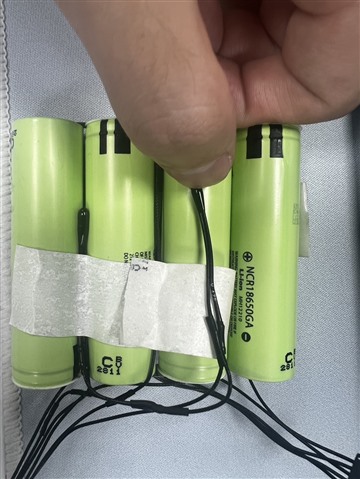
 learning_cycle.gg.csv4152.learning_cycle.log

I am encountering an issue where the SOC (State of Charge) remains stuck at 100% and does not update correctly.
I suspect this may be due to the learning cycle not having completed successfully, but I have run into several problems while attempting the learning cycle.

I’ve attached the data memory export and log files for your reference.


Issues observed during the learning cycle:

  1. TD and FD flags are not triggered, even though I have verified that the voltage and RSOC conditions have met the thresholds I configured under:
    Data Memory → Gas Gauging → FD/TD → Set Voltage Threshold.

  2. Since RSOC remains at 100% even during discharge, the gauge sometimes triggers OC (Overcurrent Discharge) protection.
    To avoid interruptions during charging and learning, I temporarily increased the OC protection threshold:
    Data Memory → Protections → OC → Threshold = 10000 mA.

  3. After fully charging the battery and entering relax mode, the [REST] flag becomes 1,
    but the [VOK] flag remains 1 and does not get cleared, and the Qmax is not updated.
    It seems the gauge is not entering the OCV update phase correctly.


I would greatly appreciate your help in identifying the possible root causes or if there's any configuration or flow I might be missing. Thank you!

  • Hello,

    This question has been assigned and will be followed up within the team.

    Thank you,
    Alan

  • Sorry, I just realized that I accidentally pressed GAUGE_EN during the beginning of the full charge phase, which may have caused the gauge to enter an incorrect state.
    I will upload a new log file as soon as possible.
    However, I want to clarify that I have previously performed a learning cycle as well, and the issues I encountered were the same.

  • Hello Kevin,

    Due to large E2E queue we trying our best to work through the question and ask for more time to work on a response.

    Thank you,
    Alan

  • Hi Kevin,

    I believe that the toggling of the GAUGE_EN at the beginning of the charge state might of reset the process for completing the Qmax update, where it would need two more relax points until it would be able to achieve one. This is most likely why it was not achieved after charge.

    How was the chemID chosen in this case?

    Regards,

    Anthony

  • I initially used a .gg configuration file left by a former colleague who is no longer with the company.
    However, this caused the SOC to display incorrectly.
    To resolve this, I restored all settings to their default values and reconfigured the .gg file according to the guidelines in the Technical Reference Manual.
    The SOC now appears to be functioning correctly, and I will proceed with the next steps of the learning cycle as outlined in the documentation.

    • Rec Temp Charging → Voltage = 4200 mV

    • Standard Temp Low Charging → Voltage

    • Standard Temp High Charging → Voltage

    • Termination Config → Charge Term Taper Current

    • Termination Config → Charge Term Voltage

    • IT Cfg → Term Voltage = 10100 mV (for 4S pack total voltage)
      Alternatively, use:
      IT Cfg → Term Min Cell V = 2525 mV (per cell threshold)

    • Design → Design Capacity mAh = 3450 mAh

    • Design → Design Capacity cWh = 4968 cWh
      (Calculated as 3450 mAh × 14.4 V ÷ 100 = 4968 cWh; note: 1 cWh = 10 mWh)

    • Current Thresholds → Dsg Current Threshold

    • Current Thresholds → Chg Current Threshold

    • Current Thresholds → Quit Current

    • Configuration → DA Configuration → CC0 = 1, CC1 = 1 (for 4S battery pack)

    • Gas Gauging → State → Qmax Cell 1~4 = 3450

    • CUV Threshold = 2475 mV
      (Prevent premature CUV protection during learning cycle)

  • Hello Kevin,

    We have received your update and are working on your response.

    Thank you,
    Alan

  • Hi Kevin,

    Understood, please share the results of the learning cycle along with how the chemID was chosen when available.

    Regards,

    Anthony

  •  I have completed the learning cycle. the SOC is displaying correctly with a maximum error of 1%. Attached are the final gg file and the execution logs.
    Next, I will proceed to calibrate the low-temperature impedance model, since our customer’s application is in space, where rapid drops in temperature may occur.

    6305.learning_cycle_complete_log.log7888.finale.gg.csv

  • Hi Kevin,

    Thanks for the update, based on the .gg file it seems like there were successful updates to the Ra Table and Qmax. Can you please confirm the temperature range that the gauge will be applied to for low temperature testing?

    Regards,

    Anthony