Other Parts Discussed in Thread: LM66200
Tool/software:
Dear TI team,
We would like to get your recommendation regarding ORing two power sources on our PCB.
Our current design involves powering the device with a single-cell 18650 Li-ion battery. A supervisor IC monitors the battery voltage, and if it falls below 3.47V, it activates a Buck-Boost power module (TPS83100). This module boosts the voltage to 5V, and this output shares the same trace as the direct battery output, ultimately feeding a 3.3V LDO.
To summarize the power source transition:
- When the battery voltage is between 4.2V and 3.47V: the Buck-Boost module is disabled (0V output), and the battery voltage directly supplies the LDO.
- When the battery voltage is between 3.47V and 3V: the Buck-Boost module is enabled (5V output) and should power the LDO instead of the direct battery voltage.
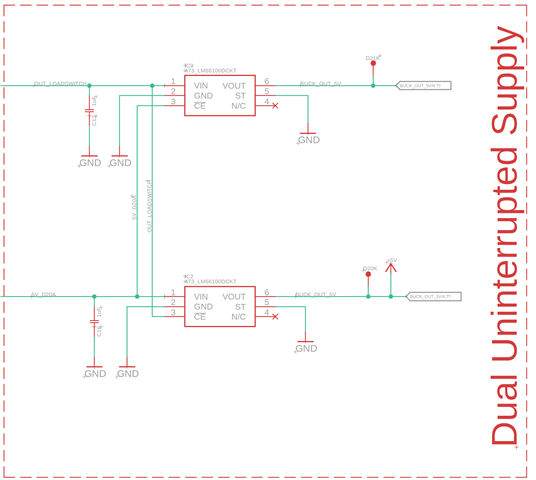
We are considering using two LM66100 ideal diode ICs to OR these two power sources (direct battery or buck-boost output) and prevent any reverse current flow. For your review, I have attached a schematic illustrating our intended connection configuration for the LM66100.
Alternatively, we noted that TI offers the LM66200, a dual-input ideal diode IC. Could you advise whether you recommend the LM66200 over the LM66100 for our specific application?