This thread has been locked.

If you have a related question, please click the "Ask a related question" button in the top right corner. The newly created question will be automatically linked to this question.

LM51551: Soft-start mechanism(s)

Part Number: LM51551
Other Parts Discussed in Thread: LM5155EVM-FLY, , LM5155, PMP22764

Tool/software:

I am designing a few different isolated flyback converters using the LM51551. I have been testing with the LM5155EVM-FLY evaluation module, but have a few questions regarding the different soft start mechanisms.


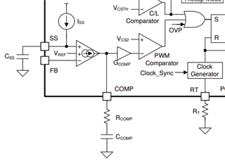
1) I'm having a hard time understanding the function of the SScap when the LM5155(1) is used in a flyback topology with isolated feedback. In documentation it is stated that the SScap is required as the primary soft start mechanism in all designs. I understand the function of the SScap in designs where the FB pin is used as the feedback of the system, however, in an isolated flyback design the FB pin is unused and the error amplifier is bypassed using the COMP pin. Does this bypassing not also make the SScap redundant in this design?


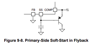
2) Why does using a primary side soft-start mechanism (shown in figure 9-8 of the LM5155x datasheet) result in an overshoot of the output voltage. In this design the SScap does make sense to me as it allows the transistor to start conducting slowly. An overshoot is a known downside of a primary side soft-start and I have observed this during testing, but I am unable to understand why this is happening. As I see it the optocoupler is not hindered by the transistor and is still able to pull down the COMP pin once the desired output voltage is required, however this does not seem to be the case.

Another (somewhat related) question I had was: Is the PGOOD pin not usable in isolated flyback designs as it is based on the FB pin?

Thanks in advance

  • Hi Lennart,

    Thanks for reaching out.

    n documentation it is stated that the SScap is required as the primary soft start mechanism in all designs.

    This is true

    in an isolated flyback design the FB pin is unused and the error amplifier is bypassed using the COMP pin.

    This is also true for SSR flybacks that are using an opto coupler.

    Does this bypassing not also make the SScap redundant in this design?

    No. The COMP pin is pulled down to GND in the beginning by the PNP transistor that is shown in the picture you attached. To slowly increase the COMP voltage, you need the SS cap.

    Why does using a primary side soft-start mechanism (shown in figure 9-8 of the LM5155x datasheet) result in an overshoot of the output voltage.

    An output overshoot should normally be avoided with using softstart.

    In this design the SScap does make sense to me as it allows the transistor to start conducting slowly.

    It allows the transistor to stop conducting slowly. (PNP)

    Can you please share your schematic? How did you implement the softstart? Are you using PSR or SSR config? 

    Another (somewhat related) question I had was: Is the PGOOD pin not usable in isolated flyback designs as it is based on the FB pin?

    Yes this is right.

    Best regards

    Moritz

  • No. The COMP pin is pulled down to GND in the beginning by the PNP transistor that is shown in the picture you attached. To slowly increase the COMP voltage, you need the SS cap.

    This I understand, but according to documentation the SS cap is also required when the PNP transistor is not present, in that case it does not make sense to me.

    It allows the transistor to stop conducting slowly. (PNP)

    You are correct, that was a typo.

    An output overshoot should normally be avoided with using softstart.

    Yes, that is also what I am trying to avoid. But I am not sure how to achieve this.

    Can you please share your schematic? How did you implement the softstart? Are you using PSR or SSR config? 

    Currently my schematic is basically equal to the LM5155EVM-FLY evaluation module. It features secondary side regulation (SSR) trough an optocoupler. I have both the primary side soft-start (PNP transistor) and the secondary side soft-start in my schematic, but I am evaluating which one (or both) I should implement in the final PCB design.

  • Hi Lennart, 

    Please take a look at the detailed App note on How to implement soft start in a flyback - https://www.ti.com/lit/an/snvaa44/snvaa44.pdf?ts=1745485576816 

    Also, attaching the reference design - https://www.ti.com/tool/PMP22764 

    I hope these helps.

    Best regards,

    Mounika

  • Thank you Mounika,

    I already had a look at both the application note and the reference design, but this did not clarify the soft-start mechanism for me. Especially since the PMP22764 reference design is not in line with the snvaa44 application note, nor the snva866a application note.

    I am probably able to get a functional flyback converter by implementing both soft-start mechanisms, like PMP22764 does. But I would like to have a better of understanding of how and why these work.

  • Hi Lennart, 

    You are right, the different documents does not completely match. 

    Let me try to clarify it:

    - When the internal error amplifier is bypassed and the COMP pin is directly used for regulation, the PNP transistor is needed. Otherwise, because of the pullup at COMP, there would be no effect of the softstart capacitor. If the pullup would not be there (This would be possible, however the bandwidh is very imited then), CSS without PNP transistor would have an effect.

    - When using PSR (primary side regulation), FB is not connected to GND, but to the voltage divider of the auxilary winding. COMP pin is then only connected to the compensation components. In this case, the PNP should be used, because the dependend on the coupling of the windings and the output capacitor used on the Aux winding, the aux winding does not perfectly reflect what is going on on the secondary side. So overshoots would be possible, even if the sofstart cap alone also has an effect on the softstart.

    -  On the flyback EVM you see that there is a SS cap use, the PNP is not placed and there is an additional secondary side soft start. 

    Indeed, the SS cap is useless when the PNP is not placed on the board. But anyway you need to connect something to this current source. 

    In case of the EVM, the R20 and C26 are enough to limit the ramp up of COMP pin, before the secondary side softstart kicks in. 

    But making this RC lower, could make the PNP necessary again. 

    What i recommend for your design:

    - Use the SS cap in combination with the PNP

    -Use the secondary side softstart

    The best reference you can follow is https://www.ti.com/tool/PMP22764  that mounika already mentioned.

    If you have further questions, please feel free to ask.

    Best regards

    Moritz

  • Hi Moritz,

    Thank you for the clarification. I have also done more testing on the evaluation module which led me to the same conclusion; using both soft-start mechanisms together is optimal. One final question remaining is how to calculate the soft-start time of the secondary mechanism. In SNVAA44 the following statement is made: "The RC time constant is given by the capacitor on the secondary side itself (C_SS,Sec) and the resistor in series
    with the optocoupler (R_OPTO,Diode)." Does this mean that the soft-start time can be calculated by simply multiplying the C_SS,Sec and the R_OPTO values?

    Thanks again

  • Hi Lennart, 

    Yes, multiplying Css_sec and R_opto will give you an estimation of the softstart time. However, the accurate calculation is very complex and i dont have a guide for it unfortunately.

    So my recommendation is to do the calculation like you said, check the real behavior in the lab and if necessary, finetune the value of Css_sec accordingly.

    Best regards

    Moritz