This thread has been locked.

If you have a related question, please click the "Ask a related question" button in the top right corner. The newly created question will be automatically linked to this question.

TPS54140A: WHY THE FREQUENCY IS NOT WHAT I SET

Part Number: TPS54140A
Other Parts Discussed in Thread: LP2951

Tool/software:

Dear team

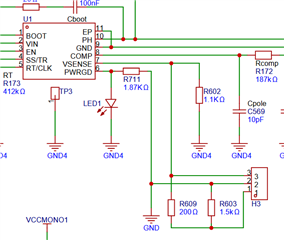
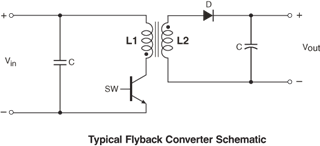
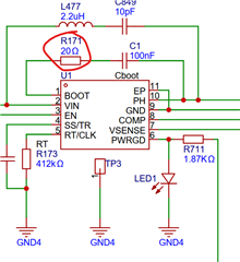
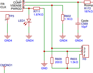
Now I use TPS54140A to design a DC-DC power supply system with isolation, the schematic is as attached.

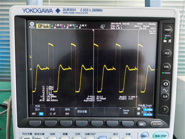
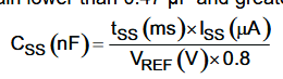
The resistance of RT is about 412KΩ, from the equation 7 in datasheet we know that the frequency should be 301kHz. But from the oscilliscope we find that the frequency is about 140kHz, about the half of what we set. Can you explain or advise what should be modified in my circuit?

The INPUT typical value is 12V, while the output VCC13) value should be 12V with Imax=1A , but when I run the system, the Vout (VCC13) will decrease to 8V or even less. I think if the frequency problem is solved, then this problem will be solved,too.

more information of my design:

we use the oscilliscope to measure the pin1 and pin4 of T404, which is a transformer and the turns ratio of the transformer is about 1:2. the inductance of the transformer is about 16uH.

Thanks

TPS54140A_20250528.pdf

  • Hi Xiowei,

    That's definetaly an interesting use of the TPS54140A. If you don't mind me asking, why is Vsense connected the way it is in the design? How is the output feeding back to the device?

    Thanks,
    Andrew

  • Hi Andrew

    Actually there is a voltage of 8 volts between GND and GND4. So Vsense does have an voltage. We can calculate that the voltage is 8/(200+1.5k+1.1k)*1.1k=3.143V.

    Regarding to the reason of this design, actually I don't understand, either. This is the design from the last engineer of my company, and we cannot contact him at all. So I send this topic to you TI engineers and want to discuss with you to see if you have experience of this design.

    Fortunately, we get the correct frequency that we expected after we change the resistance of R602 to 750Ω, and I calculate that at present the voltage of Vsense is about 2.449V. Would you please do me a favor to provide some explanations why the device working like this way?

    Regarding to the feedback question, we actually don't have feedback, so when we have an 50mA load in the output pin of LP2951, then the voltage of VCC13 is falling from more than 20V to 15V more or less. I think it is normal because it doesn't feedback. 

    Looking forward to your reply.

    Thanks.

    BR,

    Joey

  • BTW, I share the normal waveform of output of TPS54140A, it should be AC signal because it need to drive the transformer.

    Please help to show me in the picture which duration is soft start time that is determined by Css. Thanks very much.

    BR,

    Joey

  • Hi Joey,

    I will check with my team.

    Thanks,

    Andrew

  • Hi Joey

    My understanding of the circuit is that it's an inverting flybuck circuit.

    May be it would be easier to understand each piece seperatly

    inverting buck boost (Negative VOUT circuit)

    https://www.ti.com/lit/an/snva856b/snva856b.pdf

    Flybuck circuit (VOUT on primary and secondary side of the transformer)

    https://www.ti.com/lit/an/snva674c/snva674c.pdf

    I suspect that R171 may be causing the discrepancy on why FSW is not acting as it should. Could you try shorting it out, or trying a lower value and see if it affects the design.

    Thanks,
    Andrew

  • Hi Andrew

    I did two tests, changing the resistance to 10 Ω and short R171 direstly, but neither is useful to my design. Do you have any other suggestions?

    I looked through the inverting flybuck circuit, and I think this it the reason why GND is 8V high than GND4. I will read it carefully later.

    Btw, I would like to know which part is soft start duration? Would you please do me a favor to show in the waveform picture?

    Thanks and looking forward to your reply. And have a good weekend.

    BR,

    Joey

  • Hi Joey,

    For adjusting how much high GND is from GND4, you may be able to change the value by changing the resistor value or what resistor the jumper is using.

    What value do you want for GND4?

    Thanks,

    Andrew

  • Hi Andrew

    Thanks for your reply.

    8V is OK for my design. Otherwise LED1 will not work.

    Now I would like to know how to adjust the SS time, I tried to change the value of Css (C650), but nothing had happened. Did Css not work? Or actually it worked but I didn't find. So would you please do me a favor ro point out what will happen if I change the value of Css?

    Thanks.

    BR,

    Joey

  •  Hi Joey,

    Does this equation not work? What is your target soft start time?

    Thanks

    Andrew

  • Hi Andrew

    Actually I can't get the value of tss(mss) from the waveform picture. So I cannot tell whether this equation work or not.

    I changed the value of CSS from 15nF to 100nF, but the waveform didn't change. Should I change this value more bigger, e.g. 1uf?

    I'm very appreciated if you can point out which is soft start time in the picture, from where to where?

    Thanks and looking forward to your reply.

    BR,

    Joey

  • Hi Joey,

    Yeah we can try a larger value 500nF ~ 1uF capacitor. It could help.

    Thanks,

    Andrew