This thread has been locked.

If you have a related question, please click the "Ask a related question" button in the top right corner. The newly created question will be automatically linked to this question.

LP87524J-Q1: placement order of the PMIC input capacitor.

Part Number: LP87524J-Q1

Tool/software:

Hello, 

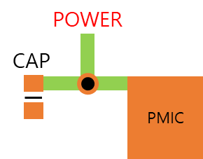
I would like to inquire about the placement order of the PMIC input capacitor.

Due to PCB space constraints, we proceeded with the artwork as shown in the attached diagram.
The decoupling capacitor (DECAP) was placed on the top layer via a via from the 3rd layer 5V power plane,
and the PMIC 5V input was connected on the bottom layer.

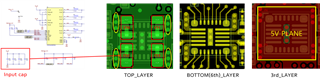
Please review and let us know if there are any issues with the DECAP placement order as shown in the attached photo.

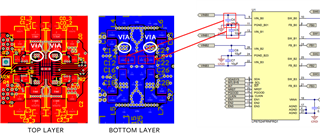
Additionally, we proceeded by referring to the reference layout on the LP8752X EVM

↓LP8752X LAYOUT

I look forward to your response.

Thank you

  • Hello Mingyu,

    Thank you for using E2E! Yes, the DECAP placement on the layout is perfectly valid. We recommend placing input capacitors as close to your PMIC as possible. Placing the PMIC and capacitors on opposite sides of the board doesn't cause any issues since the via is close to both components. This makes the LP8752X is a great reference for the design.

    Let me know if you have additional questions on your design!

    Thanks,

    Matt