This thread has been locked.

If you have a related question, please click the "Ask a related question" button in the top right corner. The newly created question will be automatically linked to this question.

TPS7H2201-SEP: Device is not working properly

Part Number: TPS7H2201-SEP

Tool/software:

Hello Team,

Im using TPS7H2201-SEP with Vin = 5V, when I assert the ENA the output is changing to 3.6mV with output capacitance of 10uF and Load of 17.5Ohm.

With the following values on the pins:

1-10 = 4.981V

11(CS) = 190mV

12(ENA) = 1.2V (asserted with different voltage source manually after VIN rises)

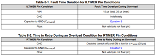
13(OVP) = 573mV (see attached picture)

14-17 = 0V(GND)

18(RTIMER) = 0.6mV (when measured with Oscilloscope it stays 0.6mV consistently)

19 = 0(GND)

20(IL) = 504mV

21(ILTIMER) = 0.6mV  (when measured with Oscilloscope it stays 0.6mV consistently)

22(SS) = 4.981V

23-33 (VOUT) = 3.6mV (instead of 5V)

* If I change the load to 4.7kOhm the output changed to ~270mV


.
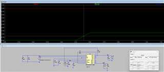
better quality for the schematic photo https://ibb.co/V0z06gQq

Measure of the OVP Pin - no overshoot above 650mV and the measured value is 573mV.

Please help me find what is wrong here.

Thanks,

Moral.

  • Hi Moral,

    I'll need some time to debug and will post an update here by the EOD, CST tomorrow

    Thanks,

    Elizabeth

  • Hi Moral,

    I'm still working on finding a solution and will update you again by EOD Monday.

    In the meantime,

    1. As shown in Tables 8-1 and 8-2 in the datasheet, RTIMER should not be connected to VIN.

    2. Is the enable being manually pulled up only for debug reasons or was it part of the original schematic before debugging?

    3. What is the reason for ILTIMER being connected to both a capacitor and VIN? This is allowed, but it is uncommon as it just programs ILTIMER to the VIN option seen in Table 8-1 of the datasheet.

    Thanks,

    Elizabeth

  • Hi Elisabeth, 

    Thanks for the quick respond, it is confusing but in the schematic picture where is noted NC in red it means Not Connected.
    Thus R69, R70 and R75 are not connected.

    Also, I tried to check it in LTSpice, by using the pSpice model from TPS7H2201-SEP page.


    It looks as if it is working properly, and the voltage for the enable to open the internal FET is near 0.65V as mentioned in the datasheet.

    Thanks,

    Moral.

  • Hi I found the problem the OVP Voltage was above the low voltage threshold, I had to change the voltage divider so it will be below it and now its working properly.

    Thanks for your help:)
    Moral.