Tool/software:
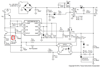
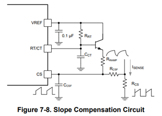
In the Datasheet of the UCC28C44 the example shows a blocking capacitor to remove DC offset when generating a ramp for slope compensation.
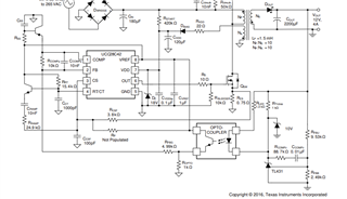
The Cramp removes the DC offset and the signal appearing at the CS pin should be a scaled version of the RC waveform of the RT/CT pin. However, when I try to probe this pin
1) the transformer starts squealing when probing the CS pin.
2) what if the load is low and the peak current doesn't turn off the comparator before the output voltage is met?
At low currents the Ramp provided by the current sense resistor is so small it appears as noise. Therefore, how does the controller regulate anything since the CS pin is the only source of a ramp to generate
the PWM? That is, if there is virtually no signal from the current sense resistor, then adding noise to the decoupled ramp yields a negative value does it not?
I hear in materials that there isn't enough ramp or there is too much, how then would I adjust this? Is the ratio purely the ratio between Rramp and Rcsf ?
If the current does go to low does the PWM converter try and operate in the Voltage Mode vs Current Mode?
Currently, I have set teh Cramp at 220nF, Rramp at 15K, Rcsf at 10K. Csf as 220pC and Rsense is 0.75ohm. The timing Resistor Rrt is 10K and Cct is 1nF.
Any information helps clarify things for me.
Thanks,
Justin