A related question is a question created from another question. When the related question is created, it will be automatically linked to the original question.
If you have a related question, please click the "Ask a related question" button in the top right corner. The newly created question will be automatically linked to this question.
Could please check with placing an electrolytic capacitor of 100 uF at the input for damping? See if it helps. Additionally, reduce inductor value to around 100 uH, currently it is quite high, it will reduce effectiveness of current control.
Hi, In my project we cannot use WET capacitor and DRY capacitor till 100uF quite expensive and there is also space issue so we cannot use more than 10uF
We tried 100uH and found efficiency to be around 80% at 60mA and again after trying 3 times, IC got burnt on direct load and thermal PAD, GND, Vin, SW pins got shorted. ( with 300uH found 90% efficiency at 60mA)
Could please share you layout files and image of the test setup also? It looks like case of Electrical Overstress (EOS) to me. Additionally, could you please probe Vin and SW with high bandwidth probe?
You can set trigger at Vin, while applying the sudden input. Probe SW and Vin together
Set trigger at Vout while applying the sudden load. Probe SW and Vout together
Moreover, share the part no./datasheet of inductor
Layout is very critical functioning of DC-DC converters. I would not recommend using Zero PCB here. Performance will be very different under both cases. On zero PCB, it will quite difficult achieve desired layout for optimizing critical loops in the converter.
Furthermore, I would recommend closely following layout recommendation for actual PCB. You use layout example given in the datasheet.


 Without load SW
 Without load Vout
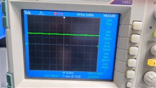 Without load Comp
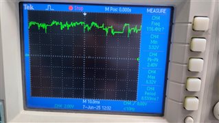 Without load BST-sw
  50mA Load Vout
 50mA Load BST-SW
 50mA Load SW
 50mA Load Comp
 55mA Load Vout
 55mA Load SW
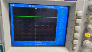 55mA load Comp
 55mA Load BST-SW
 60mA load BST-SW output-0V.
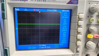 60mA load Comp output-0V.