This thread has been locked.

If you have a related question, please click the "Ask a related question" button in the top right corner. The newly created question will be automatically linked to this question.

BQ25756: Power topology review for parallel battery connections and charging

Part Number: BQ25756
Other Parts Discussed in Thread: BQ25856-Q1, CSD19532Q5B

Tool/software:

Hello,

I would like some help reviewing a topology that I intend to use utilizing BQ25756 chargers.

Below I have attached a diagram of what I want to do:

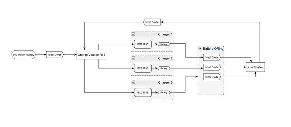
I have 3 batteries that require charging, and each of them are in parallel to power a motor driver for a ground rover. There are three batteries to allow for easy battery swap out but we also need a way for autonomous charging. 

There is a host processor on this system to control the BQ25756s through multiple I2C interfaces or a mux.

I have a list of functions that I intend for this charging system to perform:


Normal Battery Charging using external power supply

All three chargers should utilize a 60V supply and use that to charge their attached batteries and power the drive system as well keeping it alive.
The input current should be limited individually by the host processor to not exceed the rating of the power supply

Regenerative Charging

If the rover is going downhill a significant amount of energy is returned to the shared voltage bus, and I want to be able to utilize this increased voltage to charge the batteries.

The host processor can keep measuring the voltage of the shared bus and switch on the chargers as required.

Would this setup work?

Some additional info:

  • Battery Voltage max: 55V
  • Max charge current: 15A
  • Max 60V input supply current: 25A

  • Max total load: 60A
  • Max regenerative current: 20A

Any help with uncovering any major issues with this topology is greatly appreciated.

Thanks,

K

  • Hello K,

    Thanks for working on this. We've been swamped at the moment and I'll get to your question early next week.

    Best Regards,
    Ethan Galloway

  • Hello K,

    Thanks for being patient with this question.

    For normal battery charging, yes, this is would work. To limit the input current, is the host processor going to program the input current limit into each IC individually?

    Maybe the host processor can set the BQ25756 ICs' input current limit to 5A initially. Then, the host processor can increase the input current limit of the BQ25756 ICs once the batteries start entering into CV mode.

    For regenerative charging, do you know how much current/voltage will be generated by going downhill? You might be able to use the BQ25756's MPPT function to find the optimal power draw from the motors. Only 1 BQ25756 IC could use the MPPT function at a time though.

    Also, depending on your application, you can also use the BQ25856-Q1 IC. The BQ25856-Q1 is an automotive qualified version of the BQ25756.

    Let me know if you have any questions about this.

    Best Regards,
    Ethan Galloway

  • Hi Ethan,

    Thanks a lot for your help.

    Yes, the host processor can set the input currents.

    We have a local brake resistor on the motor driver to clamp the DC bus from exceeding 65V. From there the regen can be up to 20A peak if carrying heavy loads downhill. But under nominal conditions will rarely exceed 10A.

    If I set the undervoltage reference to e.g. 55V, and set VAC_DPM to be just under 60V. Will this allow all three BQ25756s to charge and regulate the charging voltage rail to around 60V during regen? Or will it have the same issue as using MPPT?

    And will this still allow the BQ25756s to charge normally with a power supply?

    And I have a couple more questions regarding protection measures of the BQ25756 below, primarily in the interests of protecting the power stage:
    * Is there overcurrent/short circuit protection on the battery charging side of the converter (assuming there is no battery connected)?

    * Is there overcurrent/short circuit protection in reverse mode?

    * Oftentimes the battery will be hotplugged/unplugged, will this cause damage to the charger while it is charging? If so, what kind of protective components can I add?

    Cheers,

    Keshav

  • Also one final question, can I use two FETs in parallel. It's not fully clear from the datasheet how strong the gate drivers are. I intend on using an external power supply to power DRV_SUP with 12V.

    The FETs I intend on using are either CSD19532Q5B or SiRS5100DP. Leaning towards the latter for lower FOM, but I'm concerned about the BQ25756 not being able to drive two of those in parallel due to a higher gate charge.

    Cheers,

    K

  • Hello Keshav,

    Yes, you can use two FETs in parallel. The gate drivers of an ON resistance of 3.4Ω and an OFF resistance of 1Ω. With a 12V gate drive supply, this would be an ON strength of 3.5A and an OFF strength of 12A.

    If I set the undervoltage reference to e.g. 55V, and set VAC_DPM to be just under 60V. Will this allow all three BQ25756s to charge and regulate the charging voltage rail to around 60V during regen? Or will it have the same issue as using MPPT?

    Setting the VAC_DPM of all three chargers might work. I think just using 1 charger at a time though would give a much reliable result though.

    And will this still allow the BQ25756s to charge normally with a power supply?

    Yes, the chargers would still be able to charge normally from the power supply.

    * Is there overcurrent/short circuit protection on the battery charging side of the converter (assuming there is no battery connected)?

    Yes, there is protection here. The charger will turn-off in the event of an over current. The charger will enter into trickle charge mode if the VBAT=0V.

    * Is there overcurrent/short circuit protection in reverse mode?

    Yes, there is protection here too. Reverse mode will turn-off if the reverse voltage falls below 80% of the target voltage or 3.3V if the bit VSYS_REV=1.

    * Oftentimes the battery will be hotplugged/unplugged, will this cause damage to the charger while it is charging? If so, what kind of protective components can I add?

    A battery voltage of 55V may cause some transient voltage spikes from being plugged and unplugged. I recommend having a set of TVS diodes of RC filters to prevent VBAT from spiking above 70V.

    Let me know if you have any questions about this.

    Best Regards,
    Ethan Galloway

  • Hello Keshav,

    Also, for the FETs, I would recommend using the CSD19532Q5B because it has a lower output capacitance. The charger needs to have the switch node capacitance less than 160nF / VIN. For a 60V application, this is 2.67nF.

    The AON66920 FET may also work for this application as well.

    Best Regards,
    Ethan Galloway