Tool/software:
Hi there,
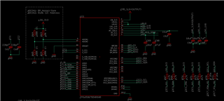
Pretty basic question - why is the TPS65987D not showing up to the host device? I have it directly wired to the EC over the i2c1 lanes, and used the standard.pjt GUI tool to flash my configuration.
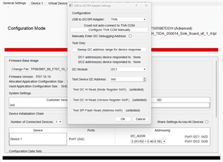
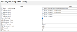
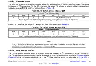
Do I need to select the correct I2C_ADDR addressing as per the resistor configuration in the General Settings configuration mode before generating the binary to flash to the SPI module?
Any help would be appreciated or direction on what settings I need to set. I would like to use it in a slave configuration only.
Regards
Ben