Other Parts Discussed in Thread: BQ34Z100-G1, GPCCHEM
Tool/software:
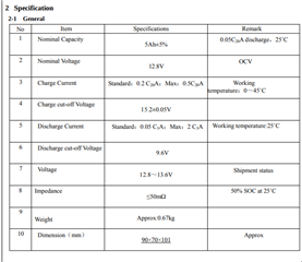
Hello, I am using the BQ34Z100EVM with this battery:
https://www.batteryspace.com/prod-specs/6865.pdf
Here is how I have the gauge programmed:
| * Field Order: Class name | Subclass name | Parameter name | Parameter Value | Display Units |
| Configuration | Safety | OT Chg | 55.0 | degC |
| Configuration | Safety | OT Chg Time | 2 | s |
| Configuration | Safety | OT Chg Recovery | 50.0 | degC |
| Configuration | Safety | OT Dsg | 60.0 | degC |
| Configuration | Safety | OT Dsg Time | 2 | s |
| Configuration | Safety | OT Dsg Recovery | 55.0 | degC |
| Configuration | Charge Inhibit Cfg | Chg Inhibit Temp Low | 0.0 | degC |
| Configuration | Charge Inhibit Cfg | Chg Inhibit Temp High | 45.0 | degC |
| Configuration | Charge Inhibit Cfg | Temp Hys | 5.0 | degC |
| Configuration | Charge | Suspend Low Temp | -5.0 | degC |
| Configuration | Charge | Suspend High Temp | 55.0 | degC |
| Configuration | Charge | Pb Temp Comp | 24.960 | % |
| Configuration | Charge | Pb Reduction Rate | 10.000 | % |
| Configuration | Charge Termination | Taper Current | 250 | mA |
| Configuration | Charge Termination | Min Taper Capacity | 25 | 1/256mAh |
| Configuration | Charge Termination | Cell Taper Voltage | 50 | mV |
| Configuration | Charge Termination | Current Taper Window | 40 | s |
| Configuration | Charge Termination | TCA Set % | 99 | % |
| Configuration | Charge Termination | TCA Clear % | 95 | % |
| Configuration | Charge Termination | FC Set % | 100 | % |
| Configuration | Charge Termination | FC Clear % | 98 | % |
| Configuration | Charge Termination | DODatEOC Delta T | 10.0 | degC |
| Configuration | Charge Termination | NiMH PbA Delta Temp | 3.0 | degC |
| Configuration | Charge Termination | NiMH PbA Delta Temp Time | 180 | s |
| Configuration | Charge Termination | NiMH PbA Hold Off Time | 100 | s |
| Configuration | Charge Termination | NiMH PbA Hold Off Current | 240 | mA |
| Configuration | Charge Termination | NiMH PbA Hold Off Temp | 25.0 | degC |
| Configuration | Charge Termination | NiMH PbA Cell Negative Delta Volt | 17 | mV |
| Configuration | Charge Termination | NiMH PbA Cell Negative Delta Time | 16 | s |
| Configuration | Charge Termination | NiMH PbA Cell Neg Delta Qual Volt | 4200 | mV |
| Configuration | Data | Design Voltage | 3200 | mV |
| Configuration | Data | Manuf Date | 1980-1-1 |
Day + Mo*32 + (Yr -1980)*256
|
| Configuration | Data | Ser. Num. | 0001 | hex |
| Configuration | Data | Cycle Count | 21 | — |
| Configuration | Data | CC Threshold | 900 | mAh |
| Configuration | Data | Max Error Limit | 100 | % |
| Configuration | Data | Design Capacity | 5000 | mAh |
| Configuration | Data | Design Energy | 6400 | cWh |
| Configuration | Data | SOH Load I | -400 | mA |
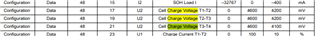
| Configuration | Data | Cell Charge Voltage T1-T2 | 3650 | mV |
| Configuration | Data | Cell Charge Voltage T2-T3 | 3650 | mV |
| Configuration | Data | Cell Charge Voltage T3-T4 | 3650 | mV |
| Configuration | Data | Charge Current T1-T2 | 10 | % |
| Configuration | Data | Charge Current T2-T3 | 50 | % |
| Configuration | Data | Charge Current T3-T4 | 30 | % |
| Configuration | Data | JEITA T1 | 0 | degC |
| Configuration | Data | JEITA T2 | 10 | degC |
| Configuration | Data | JEITA T3 | 45 | degC |
| Configuration | Data | JEITA T4 | 55 | degC |
| Configuration | Data | Volt Scale | 1 | — |
| Configuration | Data | Current Scale | 1 | — |
| Configuration | Data | Energy Scale | 1 | — |
| Configuration | Data | Device Name | bq34z100-G1 | — |
| Configuration | Data | Manufacturer Name | Texas Inst. | — |
| Configuration | Data | Device Chemistry | LION | — |
| Configuration | Discharge | SOC1 Set Threshold | 150 | mAh |
| Configuration | Discharge | SOC1 Clear Threshold | 175 | mAh |
| Configuration | Discharge | SOCF Set Threshold | 75 | mAh |
| Configuration | Discharge | SOCF Clear Threshold | 100 | mAh |
| Configuration | Discharge | Cell BL Set Volt Threshold | 2800 | mV |
| Configuration | Discharge | Cell BL Set Volt Time | 2 | s |
| Configuration | Discharge | Cell BL Clear Volt Threshold | 2900 | mV |
| Configuration | Discharge | Cell BH Set Volt Threshold | 4300 | mV |
| Configuration | Discharge | Cell BH Volt Time | 2 | s |
| Configuration | Discharge | Cell BH Clear Volt Threshold | 4200 | mV |
| Configuration | Discharge | Cycle Delta | 0.05 | % |
| Configuration | Manufacturer Data | Pack Lot Code | 0000 | hex |
| Configuration | Manufacturer Data | PCB Lot Code | 0000 | hex |
| Configuration | Manufacturer Data | Firmware Version | 0000 | hex |
| Configuration | Manufacturer Data | Hardware Revision | 0000 | hex |
| Configuration | Manufacturer Data | Cell Revision | 0000 | hex |
| Configuration | Manufacturer Data | DF Config Version | 0000 | hex |
| Configuration | Integrity Data | Static Chem DF Checksum | 5f9b | hex |
| Configuration | Lifetime Data | Lifetime Max Temp | 320.0 | degC |
| Configuration | Lifetime Data | Lifetime Min Temp | 3.3 | degC |
| Configuration | Lifetime Data | Lifetime Max Chg Current | 683 | mA |
| Configuration | Lifetime Data | Lifetime Max Dsg Current | 0 | mA |
| Configuration | Lifetime Data | Lifetime Max Pack Voltage | 13561 | 20mV |
| Configuration | Lifetime Data | Lifetime Min Pack Voltage | 3235 | 20mV |
| Configuration | Lifetime Temp Samples | LT Flash Cnt | 77 | — |
| Configuration | Registers | Pack Configuration | 0a64 | hex |
| Configuration | Registers | Pack Configuration B | 01 | hex |
| Configuration | Registers | Pack Configuration C | 00 | hex |
| Configuration | Registers | LED_Comm Configuration | 3c | hex |
| Configuration | Registers | Alert Configuration | 0000 | hex |
| Configuration | Registers | Number of series cell | 0 | — |
| Configuration | Lifetime Resolution | LT Temp Res | 1.0 | degC |
| Configuration | Lifetime Resolution | LT Cur Res | 100 | mA |
| Configuration | Lifetime Resolution | LT V Res | 1 | 20mV |
| Configuration | Lifetime Resolution | LT Update Time | 60 | s |
| Configuration | LED Display | LED Hold Time | 4 | — |
| Configuration | Power | Flash Update OK Cell Volt | 2800 | mV |
| Configuration | Power | Sleep Current | 10 | mA |
| Configuration | Power | FS Wait | 0 | s |
| System Data | Manufacturer Info | Block A 0 | 00 | hex |
| System Data | Manufacturer Info | Block A 1 | 00 | hex |
| System Data | Manufacturer Info | Block A 2 | 00 | hex |
| System Data | Manufacturer Info | Block A 3 | 00 | hex |
| System Data | Manufacturer Info | Block A 4 | 00 | hex |
| System Data | Manufacturer Info | Block A 5 | 00 | hex |
| System Data | Manufacturer Info | Block A 6 | 00 | hex |
| System Data | Manufacturer Info | Block A 7 | 00 | hex |
| System Data | Manufacturer Info | Block A 8 | 00 | hex |
| System Data | Manufacturer Info | Block A 9 | 00 | hex |
| System Data | Manufacturer Info | Block A 10 | 00 | hex |
| System Data | Manufacturer Info | Block A 11 | 00 | hex |
| System Data | Manufacturer Info | Block A 12 | 00 | hex |
| System Data | Manufacturer Info | Block A 13 | 00 | hex |
| System Data | Manufacturer Info | Block A 14 | 00 | hex |
| System Data | Manufacturer Info | Block A 15 | 00 | hex |
| System Data | Manufacturer Info | Block A 16 | 00 | hex |
| System Data | Manufacturer Info | Block A 17 | 00 | hex |
| System Data | Manufacturer Info | Block A 18 | 00 | hex |
| System Data | Manufacturer Info | Block A 19 | 00 | hex |
| System Data | Manufacturer Info | Block A 20 | 00 | hex |
| System Data | Manufacturer Info | Block A 21 | 00 | hex |
| System Data | Manufacturer Info | Block A 22 | 00 | hex |
| System Data | Manufacturer Info | Block A 23 | 00 | hex |
| System Data | Manufacturer Info | Block A 24 | 00 | hex |
| System Data | Manufacturer Info | Block A 25 | 00 | hex |
| System Data | Manufacturer Info | Block A 26 | 00 | hex |
| System Data | Manufacturer Info | Block A 27 | 00 | hex |
| System Data | Manufacturer Info | Block A 28 | 00 | hex |
| System Data | Manufacturer Info | Block A 29 | 00 | hex |
| System Data | Manufacturer Info | Block A 30 | 00 | hex |
| System Data | Manufacturer Info | Block A 31 | 00 | hex |
| Gas Gauging | IT Cfg | Load Select | 1 | — |
| Gas Gauging | IT Cfg | Load Mode | 0 | — |
| Gas Gauging | IT Cfg | Max Res Factor | 50 | — |
| Gas Gauging | IT Cfg | Min Res Factor | 1 | — |
| Gas Gauging | IT Cfg | Ra Filter | 500 | — |
| Gas Gauging | IT Cfg | Min PassedChg NiMH-LA 1st Qmax | 50 | % |
| Gas Gauging | IT Cfg | Maximum Qmax Change | 100 | % |
| Gas Gauging | IT Cfg | Cell Terminate Voltage | 2500 | mV |
| Gas Gauging | IT Cfg | Cell Term V Delta | 200 | mV |
| Gas Gauging | IT Cfg | ResRelax Time | 500 | s |
| Gas Gauging | IT Cfg | User Rate-mA | 0 | mA |
| Gas Gauging | IT Cfg | User Rate-Pwr | 6400 | cW |
| Gas Gauging | IT Cfg | Reserve Cap-mAh | 256 | mAh |
| Gas Gauging | IT Cfg | Reserve Energy | 51200 | cWh |
| Gas Gauging | IT Cfg | Max Scale Back Grid | 20 | — |
| Gas Gauging | IT Cfg | Cell Min DeltaV | 803 | mV |
| Gas Gauging | IT Cfg | Ra Max Delta | 7 | % |
| Gas Gauging | IT Cfg | Design Resistance | 2085 | mOhm |
| Gas Gauging | IT Cfg | Reference Grid | 90 | — |
| Gas Gauging | IT Cfg | Qmax Max Delta % | 50 | mAh |
| Gas Gauging | IT Cfg | Max Res Scale | 3940 | — |
| Gas Gauging | IT Cfg | Min Res Scale | 24576 | — |
| Gas Gauging | IT Cfg | Fast Scale Start SOC | 160 | % |
| Gas Gauging | IT Cfg | Charge Hys V Shift | 10241 | mV |
| Gas Gauging | IT Cfg | Smooth Relax Time | -3072 | s |
| Gas Gauging | IT Cfg | TD Delay | 0 | s |
| Gas Gauging | IT Cfg | Max DeltaV Limit | 0 | mV |
| Gas Gauging | IT Cfg | DeltaV Filter | 240 | — |
| Gas Gauging | Current Thresholds | Dsg Current Threshold | 60 | mA |
| Gas Gauging | Current Thresholds | Chg Current Threshold | 75 | mA |
| Gas Gauging | Current Thresholds | Quit Current | 40 | mA |
| Gas Gauging | Current Thresholds | Dsg Relax Time | 60 | s |
| Gas Gauging | Current Thresholds | Chg Relax Time | 60 | s |
| Gas Gauging | Current Thresholds | Cell Max IR Correct | 400 | mV |
| Gas Gauging | State | Qmax Cell 0 | 5000 | mAh |
| Gas Gauging | State | Cycle Count | 0 | — |
| Gas Gauging | State | Update Status | 00 | — |
| Gas Gauging | State | Cell V at Chg Term | 14203 | mV |
| Gas Gauging | State | Avg I Last Run | -299 | mA |
| Gas Gauging | State | Avg P Last Run | -1131 | cW |
| Gas Gauging | State | Cell Delta Voltage | 2 | mV |
| Gas Gauging | State | T Rise | 20 | — |
| Gas Gauging | State | T Time Constant | 1000 | — |
| Ra Table | R_a0 | R_a0 Flag | ff55 | hex |
| Ra Table | R_a0 | R_a0 0 | 0 | — |
| Ra Table | R_a0 | R_a0 1 | 0 | — |
| Ra Table | R_a0 | R_a0 2 | 0 | — |
| Ra Table | R_a0 | R_a0 3 | 0 | — |
| Ra Table | R_a0 | R_a0 4 | 0 | — |
| Ra Table | R_a0 | R_a0 5 | 0 | — |
| Ra Table | R_a0 | R_a0 6 | 0 | — |
| Ra Table | R_a0 | R_a0 7 | 0 | — |
| Ra Table | R_a0 | R_a0 8 | 0 | — |
| Ra Table | R_a0 | R_a0 9 | 0 | — |
| Ra Table | R_a0 | R_a0 10 | 0 | — |
| Ra Table | R_a0 | R_a0 11 | 0 | — |
| Ra Table | R_a0 | R_a0 12 | 0 | — |
| Ra Table | R_a0 | R_a0 13 | 0 | — |
| Ra Table | R_a0 | R_a0 14 | 0 | — |
| Ra Table | R_a0x | R_a0x Flag | ffff | hex |
| Ra Table | R_a0x | R_a0x 0 | 0 | — |
| Ra Table | R_a0x | R_a0x 1 | 0 | — |
| Ra Table | R_a0x | R_a0x 2 | 0 | — |
| Ra Table | R_a0x | R_a0x 3 | 0 | — |
| Ra Table | R_a0x | R_a0x 4 | 0 | — |
| Ra Table | R_a0x | R_a0x 5 | 0 | — |
| Ra Table | R_a0x | R_a0x 6 | 0 | — |
| Ra Table | R_a0x | R_a0x 7 | 0 | — |
| Ra Table | R_a0x | R_a0x 8 | 0 | — |
| Ra Table | R_a0x | R_a0x 9 | 0 | — |
| Ra Table | R_a0x | R_a0x 10 | 0 | — |
| Ra Table | R_a0x | R_a0x 11 | 0 | — |
| Ra Table | R_a0x | R_a0x 12 | 0 | — |
| Ra Table | R_a0x | R_a0x 13 | 0 | — |
| Ra Table | R_a0x | R_a0x 14 | 0 | — |
| Calibration | Data | CC Gain | 10.123 | mohm |
| Calibration | Data | CC Delta | 10.147 | mohm |
| Calibration | Data | CC Offset | -1294 | — |
| Calibration | Data | Board Offset | 0 | — |
| Calibration | Data | Int Temp Offset | 0.0 | degC |
| Calibration | Data | Ext Temp Offset | 0.0 | degC |
| Calibration | Data | Voltage Divider | 55786 | mV |
| Calibration | Current | Deadband | 5 | mA |
| Security | Codes | Sealed to Unsealed | 36720414 | hex |
| Security | Codes | Unsealed to Full | ffffffff | hex |
| Security | Codes | Authen Key3 | 01234567 | hex |
| Security | Codes | Authen Key2 | 89abcdef | hex |
| Security | Codes | Authen Key1 | fedcba98 | hex |
| Security | Codes | Authen Key0 | 76543210 | hex |
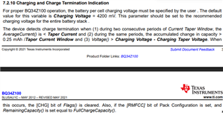
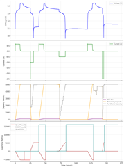
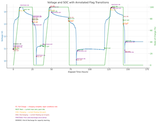
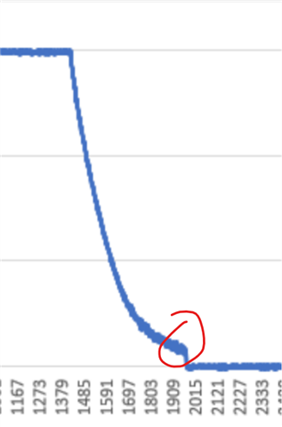
My problem is that the gauge seems to intermittently be setting FC prematurely so I can't actually charge it past around 13344 mV.
This is my first time working with a battery in this manner, so I fully accept that this is likely going to be due to user error. Can you help me spot some misconfiguration or give me some leads on why this may be happening? Any advice on anything else I screwed up is welcome.
Thanks!