Tool/software:
Dear TI Support Team,
I hope this message finds you well.
I am currently evaluating the TPSI31PXQ1EVM for a pre-charge application and would like to confirm a few details:
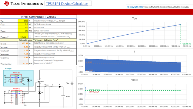
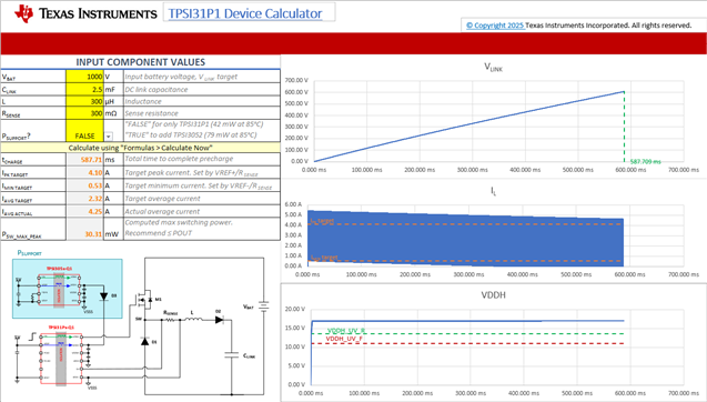
1. Voltage Support: Can TPSI31PXQ1EVM reliably support for input voltage of 1000V?
2. DC link Parameter: This application involves DC link capacitor of 2500uF, targeting a pre-charge duration approximately 2 seconds, could you please confirm if TPSI31PXQ1EVM is suitable for this configuration?
3. Pre-Charge Time Setting: While referring to the calculation sheet provided on the product page, I have noticed that it does not allow me to manually set or select the required pre-charge time. Kindly advise how this value be configured or if an updated tool is available.
reference: (https://www.ti.com/tool/TPSI31PXQ1EVM)
4. Could you also please provide application note on component selection and calculation.
Best Regards,
Suraj Singh