Tool/software:
Hi TI technical team,
We design a Vin 1.8V to 1V LDO circuit with 0.8A TDC current, but the datasheet not shown current limit waveform for reference.
There is a question about the current limit waveform.
Q1: can we using E-load for the current limit test?
Q2: If not, please suggest how to test current limit item?
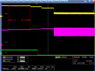
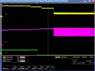
Q3: We see the PG(CH4) drop when Vout equal to 0.9V, is the waveform we can consider it is current limit waveform?
CH1: VOUT, CH3: IOUT, CH4: PG
Thanks for your reply.