A related question is a question created from another question. When the related question is created, it will be automatically linked to the original question.
If you have a related question, please click the "Ask a related question" button in the top right corner. The newly created question will be automatically linked to this question.
Thank you for reaching out to TI with your questions regarding the UCC27524A.
We do have a newer version of this part that is the UCC27624 that is pin-to-pin and features a wider VDD operating range as well.
Looking at the schematic, I have a few questions and comments.
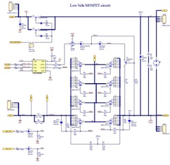
1. For the inputs (INA/INB), we recommend an RC filter for noise filtering that is 0-100 Ohms and 10-100pF placed close to the gate driver.
2. For the VDD supply, we recommend to have two local bypass capacitors for this pin. One that is a 0.1uF and one that is at least 1uF. See Section 8 Power Supply Recommendations in the datasheet for more information.
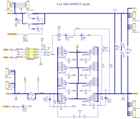
3. The gate resistances (R21, R23 and the 47 Ohm at each FET) are significantly larger than expected and will greatly slow down rise/fall times especially with the FETs in parallel.
4. What is the operating conditions and need for Q4, D13, D14, and Q5?
5. The pulldown resistance of R42 and R39 of 10 MOhms is much larger than we typically see. At that size it would likely not have much impact, these are typically 10 kOhms or a little larger like up to 100 kOhms.
6. Is SGND and BAT- ever connected? The gate driver will need a source reference for the FETs in order to drive the gate.
The gate resistances (R21, R23 and the 47 Ohm at each FET) are significantly larger than expected and will greatly slow down rise/fall times especially with the FETs in parallel.
Ans. have used a larger one before, and tidmb17 uses 75R
What is the operating conditions and need for Q4, D13, D14, and Q5?
Ans. This circuit is used to accelerate the closing of CHG-MOS. In fact, many of them are based on the reference circuit of tidmb17. I attach the file.
The pulldown resistance of R42 and R39 of 10MOhms is much larger than we typically see. At that size it would likely not have much impact, these are typically 10kOhms or a little larger like up to 100kOhms.
Ans. The same BMS I used before also works with 10MOhms
It is okay to use larger resistances for the gate resistors as long as the rise and fall times are acceptable for the application. This is not an inherent risk to the circuit.
The 10MOhms pulldown on the gate is okay, it is just rather weak and so will not provide much pulldown strength if needed. This is okay to leave as 10MOhms as this is not a required component, it is optional. The driver will pulldown the gate as well.