This thread has been locked.

If you have a related question, please click the "Ask a related question" button in the top right corner. The newly created question will be automatically linked to this question.

BQ25185: Multiple charger IC in parallel for 1S6P battery

Part Number: BQ25185
Other Parts Discussed in Thread: LM66200

Tool/software:

Hello

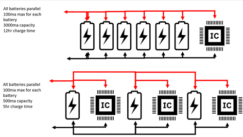
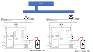
I am currently working on creating a custom battery pack for my application. I am using some specialized high temperature batteries in a 1S6P configuration. These batteries have a low charging maximum of 100ma, a 4.1v maximum, and a capacity of 500ma. I would like to use the BQ25185 circuit to charge these batteries. However, the combined capacity is about 3000mah. Each battery can charge at a maximum of 100ma, but I need to make sure that charging current is distributed evenly. My question: Is it possible to put multiple BQ25185 chargers in parallel each with its own cell for faster charging? See attached.

  • Hi Eric,

    The BQ25185 supports up to a 1A charge current, so a single BQ25185 can charge a 1s6p pack at 600mA. If multiple BQ25185s are paralleled, each supplying 100mA, the total charge current remains 600mA and the pack charges at the same rate.

    The battery regulation voltage can be set to 4.1V by an external resistor on the ILIM/VSET pin.

  • Is there an available circuit diagram with multiple BQ25185 chips in parallel?

  • Hi Eric,

    We don't currently have a circuit diagram with multiple BQ25185s in parallel, but it should be possible to do this. I'd be interested to hear more about your motivation for using chargers in parallel - are you looking to reduce temperature rise by spreading power dissipation across multiple chargers?

    The main consideration is all of the chargers being in constant voltage (CV) mode at the same time. In constant current (CC) mode, the BAT pins act like current sources, so all of the charge currents simply add together. However, in CV mode, the BAT pins act like voltage sources, each trying to regulate the BAT node, which could lead to instability or oscillations and cause issues with charge termination.

    The strategy is to set staggered battery regulation voltages for each charger. For example, if using 2 chargers in parallel, you can set VBATREG of one charger to 4.05V and the other to 4.1V - since your max battery voltage is 4.1V. This way, there are never multiple chargers in CV mode at the same time, and only one charger will handle charge termination.

    Another consideration is the SYS pin. I'd recommend connecting your system load to only one of the SYS pins rather than tying them all together. The other SYS pins would just need their capacitors for stability.

    Let me know if you have any questions. 

    Best regards,

    Alec

  • Hello Alec
    The goal of this design is to enable a faster charge time for the battery pack. The manufacturer of the batteries states the maximum charging current for 2 or more cells in parallel to be 250ma. This would result in quite the long charge time for a 3000mah pack. I wanted to give each battery its own charging circuit so that each one can do 100ma without worrying about one battery getting too much current at once. I think what I really need is a diode on the sys pin going to the system load. I believe this will allow me to keep the batteries separate for charging purposes but still allow all of them to supply power to the load. I was looking at the LM66200 chip from TI for this. Also, I'm not sure if the Q3 FET pins are going the correct direction in the block diagram. Shouldn't the battery pin be connected to the drain on the FET to enable the chip to control the battery output?

  • Hi Eric,

    Thanks for clarifying. If I understand correctly, you aren't necessarily connecting multiple BQ25185s in parallel, but rather using one BQ25185 per pack.

    The block diagram looks good. You're correct that ideal diodes are needed between the SYS pins of each charger and the system load. The LM66200 seems like a good choice here. If you need help selecting an ideal diode, I'd recommend posting a separate E2E with that part number.

    The functional block diagram in the datasheet is a high-level abstraction - the actual BATFET (Q3) circuitry is much more complex than what's shown.

    Best regards,

    Alec