This thread has been locked.

If you have a related question, please click the "Ask a related question" button in the top right corner. The newly created question will be automatically linked to this question.

TPS25751: USBC PD with data support

Part Number: TPS25751
Other Parts Discussed in Thread: TPS25814, , BQ25731, TPD6S300, TPS26750, BQ25756, TPS25750

Tool/software:

We have an application that will charge a USBC laptop at 65W while supporting a data channel.  The data source would be an Ethernet to USB bridge. 24VDC is available to generate the charging voltages.  The ideal solution would require no host MCU interaction to keep costs low.  Low development effort and quick time to market are also critical.  The TPS25751 appears to be a good fit, possibly the TPS25814 as well.  Can the USB data from the Ethernet bridge be fed directly to the USB-C connector instead of the BC 1.2 from the TPS25751 or TPS25814.  Or is there a better topology/more preferred approach?  Thank you for your help.  

  • Hello,

    Can the USB data from the Ethernet bridge be fed directly to the USB-C connector instead of the BC 1.2 from the TPS25751 or TPS25814. 

    If you do not need BC1.2 then the data can be fed directly.  Please be advised there are variants of BC1.2 which use time division multiplexing to first establish the battery charging protocol and then free the lines for data.

    The ideal solution would require no host MCU interaction to keep costs low.

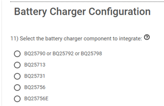
    These devices are not intended for source only applications so there will be some additional effort and cost to address.  Additionally, an MCU of some kind would be required to serve as an interface between the PD controller and BUCK regulator stepping down the 24V to the negotiated contract (5,9,15,20).  If you look at the current GUI configuration tool you will see the current BQ devices with which we have integrated the interface drivers into the PD controller.

    USBCPD Application Customization Tool

    Regards,
    Chris

  • Hi Chris,

    Thank you for the quick reply.

    We do not need BC 1.2 or liquid detection.

    For our application, which is PD source only, can the configuration be handled with external EEPROM so no MCU is required?

    Can the BQ25731 be used as the regulator to generate the PD source 5-20V from our 24VDC in w/o using the battery charging function?  We would simply use it as a buck regulator.  It appears the TPS25751 supports both EEPROM and BQ25xxx simultaneously (EEPROM at boot, then charger during normal operation)?

    Is there a better PD controller alternative from TI that you would recommend?  The selector guide shows this as the only option for 65W+.

    Thank you for your help.

    Steve

  • Hello,

    For our application, which is PD source only, can the configuration be handled with external EEPROM so no MCU is required?

    Correct.  You can use and external EEPROM.

    Can the BQ25731 be used as the regulator to generate the PD source 5-20V from our 24VDC in w/o using the battery charging function?  We would simply use it as a buck regulator.  It appears the TPS25751 supports both EEPROM and BQ25xxx simultaneously (EEPROM at boot, then charger during normal operation)?

    Yes.  But I will double confirm this has been tested.

    It appears the TPS25751 supports both EEPROM and BQ25xxx simultaneously (EEPROM at boot, then charger during normal operation)?

    Yes, this is correct.

    In the dead battery case the PD controller will enable the Type-C terminations as a sink.  If the port partner has a dual role capability, then the port partner will become the source and the TPS25751 the sink.  You could potentially prevent the sink terminations by using a port protection device like the TPD6S300 or even prevent the EEPROM from loading until VIN_3V3 is present but each of these have tradeoffs (and not completely vetted) and are outside of the original intent of the device.

    Is there a better PD controller alternative from TI that you would recommend?  The selector guide shows this as the only option for 65W+.

    Not at this time.  We are working to fill these portfolio gaps.

    Regards,
    Chris

  • Can the BQ25731 be used as the regulator to generate the PD source 5-20V from our 24VDC in w/o using the battery charging function?  We would simply use it as a buck regulator.  It appears the TPS25751 supports both EEPROM and BQ25xxx simultaneously (EEPROM at boot, then charger during normal operation)?

    Yes.  But I will double confirm this has been tested.

    Hi Chris,

    Just following up to see if there are any concerns using the BQ25731 in this manner?  We are creating the prototype schematic.  Is there an opportunity to have you review before we send out for PCB's?

    Thanks again for your help.

    Steve

  • Hello,

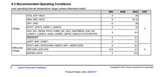
       My apologies for the delay and the incorrect information.  The BQ25731 is outside of my product space but I can see that the recommended operating conditions have a maximum of 23.15V for VSYS, so 24V would not work.

    What has been tested is articulated in this reference design.

    Regards,

    Chris

  • Hi Chris,

    I believe you were initially correct on the BQ25731 - the allowable input Vbus is 26V which will work with our 24VDC supply input.  Max Vsys of 23.15V is the supply for battery charging and to the TPS25751 if I am reading the datasheet correctly.

    My concern right now with the TPS25751 is that the EVM is no longer available.  That being the case, I wanted to run two other options by you:

    1. Use the TPS26750 with BQ25756 although the TPS EVM also has limited availability.

    2. Use the TPS25763.  This has an integrated DC/DC so does not require a separate boost/buck.  The options available as a result of the display port might also make it more appropriate for use with our data channel.  It has a maximum input of 18VDC, but it would be more straightforward for us to use a 12VDC input if the USBC aspect is streamlined significantly.  The EVM is also readily available.  I would lean toward this approach if you agree.

    Thoughts?

    Thanks again for being so responsive.

    Steve

  • Hello,

    The TPS25751 (and the TPS25750) automatically configure the BQ25731 based upon if the TPS25751 is in sink or source mode.  In the sink mode the TPS sends to the BQ via I2C the commands to disable OTG and enable charging.  

    https://www.ti.com/lit/ds/symlink/bq25731.pdf#page=42  write 0x0E to regiter 0x00

    in source mode 

    write 0x0F to register 0x00

    write 0x14 to register 0x35

    My concern is that you are using the BQ25731 in a direction that is opposite what the TPS25750/1 is expecting.  You would need to bypass the I2C events of the TPS25750/1 and use an MCU to control the BQ part based upon the negotiated contract.  

    2. Use the TPS25763.  This has an integrated DC/DC so does not require a separate boost/buck.  The options available as a result of the display port might also make it more appropriate for use with our data channel.  It has a maximum input of 18VDC, but it would be more straightforward for us to use a 12VDC input if the USBC aspect is streamlined significantly.  The EVM is also readily available.  I would lean toward this approach if you agree.

    I would agree.  I have requested a colleague to comment.

    Source only.  SPR range. Support USB3 data.

    Regards,

    Chris