This thread has been locked.

If you have a related question, please click the "Ask a related question" button in the top right corner. The newly created question will be automatically linked to this question.

BQ25792: Charge Current only ~50mA

Part Number: BQ25792

Tool/software:

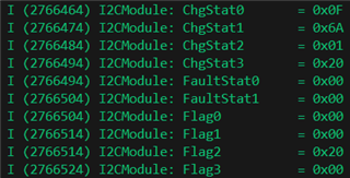
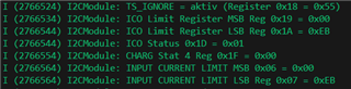
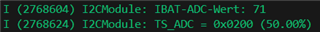
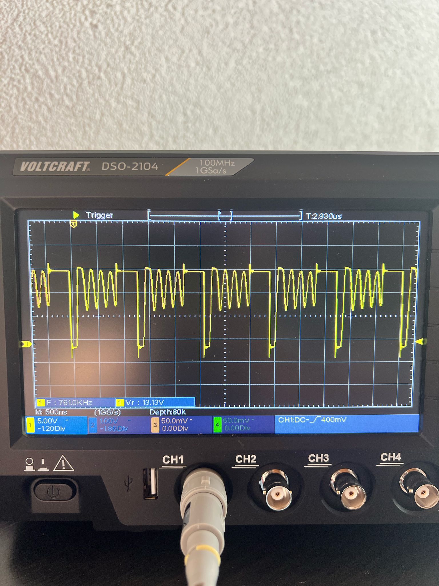
Charge Current wont Rise to the expected value of about 2.35A acording to the set Value via the ILIM Resistor and the I2C Register Values.
Charger is in Fast Charge Mode, supplied with 5V or 12V it only charges the Battery with a few Milliamps. Battery Connected is 3S LI Ion 12V.
Stat Pin is Low, CE is pulled to GND. No Ship Fet, no ACDRV Fet.


  • Hi Bastian,

    I don't see any obvious errors on the schematic except for SDRV.  We found that SDRV cannot be connected to BAT pin and must be tied to ground through a 1000pF capacitor like on the EVM.  Otherwise the SDRV charge pump switching noise interferes with the BATFET charge current measurement.  The input current limit register is clamped by the ILIM_HIZ resistor divider unless the EN_ILIM bit is changed to 0.  For ICHG =2.35A, you would need IINDPM > VBAT*2.35A/VIN.  I was unclear if the ICO limit register above was a read out or a write.

    A few mA charge current is too low even factoring in SDRV =BAT.  With VBUS applied, I assume REGN comes up to 5V?  Do you have an oscilloscope to confirm that SW1 and/or SW2 are square-ish waveforms switching at 750kHz? 

    Regards,

    Jeff 

  • Hello Jeff,

    First of all thank you for your reply. The SDRV Connection to BAT is unfortuantely directly under the chip, so i cant change that easily. The Input Current Limit register was a read which showed the same value 0XEB like on the Input Current Limit Register. The Value should be from the ILIM_HIZ Resistor devider. 

    When VBUS is applied, the 5V REGN comes up without a Problem. Here Are some OSZI Shots from the SW1 Pin. Something isn't right it seems with a Frequency of about only 60kHz. Do you have an idea why?

  • HI Bastian,

    If PFM is enabled and the load is light, the switching frequency is a function of load not fixed 750kHz in order to improve efficiency.  To prove that SDRV = BAT isn't the problem, can you disable PFM (REG0x12[4]) and/or apply a load at 1A or higher on SYS.  If the converter can supply that load but can't charge at that current, then the BATFET CSA is measuring incorrectly.  

    Regards,

    Jeff

  • Hello Jeff,

    I now changed the PFM Bit, it didnt Change the Charging Current Problem, but on the Oscilloscope I was measuring the 750kHz on The SW1 Pin. But what seemed strange to me is, that on the SW2 Pin a Constant Voltage of 12V was present, seemed to be VBat. What do you mean with BATFET CSA measurement? and what can i do about it? I thank you very much for helping me with this problem

    Best Regards,

    Bastian

  • Hi Bastian,

    The current sense amplifier (CSA) converts current flow across the internal BATFET between SYS and BAT into a voltage.  The constant current analog feedback loop uses this voltage to regulate the charge current to the correct value.  The noise from the SDRV output tied to BAT pin has been known to make the CSA think that higher current is flowing.  To prove my theory, you might try adding a 0.1uF capacitor in parallel with the 10uF BAT capacitor that is closest to the IC to filter some of that noise.  If the charge current increases at all with SDRV=BAT is the issue.

    Regards,

    Jeff

  • Hi Jeff,

    I soldered a 0.1uF cap directly to the Chips Bat/SDRV Pin and to GND. The IBAT-ADC Value came up to 80mA instead of 75mA as before. do you think this little difference is enough? 

    Best Regards,

    Bastian

  • There is actualy still quite some ripple on BAT. AC Coupling on the oscilloscope. Measured with the 0,1uF Cap

  • Hi Bastian,

    That cap may not help enough, be filtering the wrong frequency (need to be smaller) or this isn't the issue.  Are you able to place a load on SYS to confirm that the converter can output a higher current?  This would eliminate the converter itself as the problem.

    Regards,

    Jeff

  • Hi Jeff,

    How much Current should I draw? with Battery connected or disconected? With Battery connected i already tested a nother part of the PCB which is powered by SYS VCC and was able to draw about 3,5A.

    Best Regards,

    Bastian

  • Hi Bastian,

    You can estimate max output current using a power balance, so efficiency = VSYS*ISYS/VIN*IINDPM.  But if you can get a high current out of SYS that is not being supplemented by battery discharge current, the converter is working as expected.  With enough input power, the 792 can provide easily provide over 4A before its package and therefore die gets too hot, causing the thermal regulation loop to reduce current.

    Regards,

    Jeff

  • Hi Jeff,

    I now used a 4 Ohm Power Resistor without the Battery Connected. The SYS VCC was Stable at 9,4V. When using an 2Ohm Power Resistor the Sys VCC went to 8,6V. So I think the converter is working properly or am I wrong? Power was Supplied by USB C-PD at 15V 2A. 

    Best Reguards,

    Bastian

  • Hi Jeff,

    I was able to cut the connection between SDRV and BAT and connect the 1000 pF capacitor to GND. It works perfectly — the charge current immediately regulates to 1 A without any I2C communication, just as it should.

    Thank you very much for your support!

    Is there a way I could send you a small token of appreciation?

    Best regards,


    Bastian

  • HI Bastian,

    You are welcome.  Your small token can be more charger purchases! Ha!

    Regards,

    Jeff