This thread has been locked.

If you have a related question, please click the "Ask a related question" button in the top right corner. The newly created question will be automatically linked to this question.

TPS2596: Current limit case and thermal shutdown..

Part Number: TPS2596

Tool/software:

Hi team,

I am promoting TPS259631 to my customer and have one question/concern.

They use 12V / 1A limit and PCB has coated with a kind of Resin to proof the water.

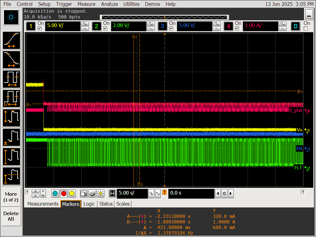
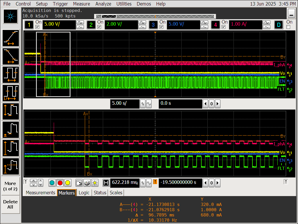
The concern is once the currents exceed 1A (like 2A) then TPS2596 is trying to limit the currents and this dissipated power cause thermal until TSD(+157C/typ) and retry it with its hysteresis(11.5C) this thermal will cause to melt their Resin. (This is the issue)

Are there any idea that the IC temperature not to go high to prevent to melt the Resin?

(There's TPS259630 which has Latch off type but this need EN control.) 

Bests, 
Ernest

  • Hi Ernest,

    When device limits the current, it will have to dissipate the excess heat and that will cause junction temperature to rise. This is true for any current limiting device. 

    Are they primarily concerned about repeated thermal shutdown and retry which is causing the resin to melt?

    I am not sure what we can do here. The power dissipation here is decided by the customers use case. limiting the current at ILIM, Vout will almost become 6V (in case of Rload = 6Ohms). The power dissipation will be 6W. 

    You should check with them if the test condition of 2A load for long duration a realistic scenario? If this is not realistic scenario, then they should first calculate the expected power dissipation and temperature of ic. 

    (There's TPS259630 which has Latch off type but this need EN control.) 

    Yes, the latch off device won't perform retries so yes average power dissipation will be lesser. 

    Best Regards,
    Arush

  • Hi Arush,

    Thanks for your feedback. I am on the same page with you. 2A load case would not be a real scenario for them in the normal case.
    But they are care for the abnormal cases.

    Could your team help to get a data of Tj(junction) vs Tc(case) for such a OCP cases? (1A limit then 1.5A, 2A, 3A current case)
    ie) Tc temp when Tj reaches 150C if currents +1A(6W) exceeded?

    Can you support any test result, simulation or equation?

    Best Regards,
    Ernest

  • Hi Arush,

    I've checked with EVM and temperature saturated < 60C at over current case.

    And current level during auto-retry is about 300~350mA, not 1A, and Vout is stayed 0V.
    This is not the same graph with Figure 48 in the datasheet.

    I've seen "current limit foldback" feature, is it due to the foldback?

    Best Regards,
    Ernest

  • Hi Ernest,

    I've checked with EVM and temperature saturated < 60C at over current case.

    How much load was applied?

    I've seen "current limit foldback" feature, is it due to the foldback?

    We should not see this much current foldback for this device.

    Could your team help to get a data of Tj(junction) vs Tc(case) for such a OCP cases? (1A limit then 1.5A, 2A, 3A current case)
    ie) Tc temp when Tj reaches 150C if currents +1A(6W) exceeded?

    I am checking on this. I will get back to you early next week on this.

    Also can you confirm if customer is open to changing the device. Also as you also agree that this won't be a realistic scenario. Can you tell me what is there realistic scenario expectation and how much buffer do they want.

    Also do they want current limiting device or circuit breaker device?

    Best Regards,
    Arush

  • Hi Arush,

    How much load was applied?

    I tested 1.5A and 2.5A load at 1A limit condition with EVM. Same situation with 1.1A, 1.5A, 2.5A.

    As you see below waveforms, this limited ~320mA and retry after ~96ms.

    1.5A Over current (1A limit)

  • Hi Arush,

    Any updates for Tj vs Tc relationships?

    Bests, 
    Ernest

  • Hi Arush,

    I've sent an email for reviewing their layouts to you.
    Would you also see and give your feedback?

    Thank you.

  • Hi Ernest, 

    I have responded to the email.

    I forgot to add Tj Tc information

    Tjc (top) when thermal pad soldered --> 22.7

    Tjc (top) when thermal pad not soldered --> 50.4

    Best regards,
    Arush

  • Hi Arush,

    We should not see this much current foldback for this device.

    When I saw the output current waveform, it is not 1A which I set up the currents limit, but it is 320~350mA.

    I've seen current limit foldback graph in the datasheet for 125mA and 2A I_limit. (Figure 22, Figure 23). 

    www.ti.com/lit/gpn/tps2596 


    For 2A I_limit and 12V at 20C, its foldback current is around 770mA.
    So I assume if I_limit become 1A, it is around 330mA and this is similar result of mine.

    So I thought the retry currents of 320mA on above waveform is foldback current.

    My thinking is wrong?

  • The waveform above, Vo (Yellow) is stay 0V even 320mA output current exist.

    Can we explain this? otherwise is it due to the set up? (E-Load CC mode)

    Best Regards,
    Ernest

  • Hi Ernest,

    This is indeed strange. I thought you applied output short in the waveform hence you are not seeing the Vout.

    Can you reverify if there is no output short. Also, can you use CR mode instead of CC mode.

    Best Regards,
    Arush