Tool/software:
- Component Information
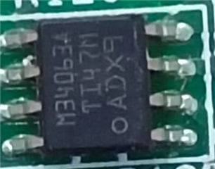
- Part Number: MC34063A
- Batch Code : [OADX9, PKSOA, PYRRA]
- Application Details
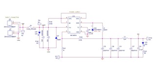
- Application Type: Step-down (Buck) Converter
- Input Voltage (Vin): 36V DC
- Output Voltage (Vout): 5V DC
- Load Current: 510mA (Continuous)
- External Components:
- Inductor: 220uH
- Diode: Vishay, SS34-E3/57T
- Issue Description
we are observing a frequent failure of the MC34063A IC during operation under the above-mentioned conditions. When a continuous load of approximately 510mA is applied, the IC becomes excessively hot and eventually gets damaged (burnt). This has occurred repeatedly across multiple units. - Observations
- Failures are consistent under sustained load above 500mA.
- IC temperature rises rapidly during operation.
- Burn marks are visible in some cases.
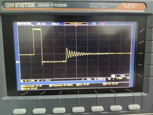
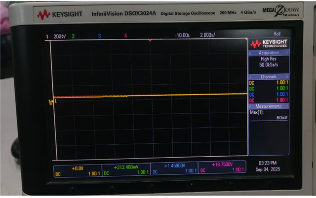
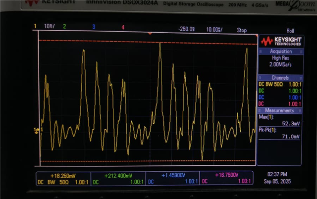
- No significant voltage spikes or transients observed on input/output lines.
- Input voltage remains stable at 36V.
We kindly request your support in investigating this issue at the earliest, as this is affecting our production stability.
Looking forward to your feedback.