This thread has been locked.

If you have a related question, please click the "Ask a related question" button in the top right corner. The newly created question will be automatically linked to this question.

BQ34Z100-R2: Issue with BQstudio configuration and learning cycle for 50Ah 24V LFP battery

Part Number: BQ34Z100-R2
Other Parts Discussed in Thread: BQSTUDIO, GPCCHEM, BQ34Z100

Tool/software:

Hi everyone,

I am working on completing a successful learning cycle for a CANBAT LFP battery, which is 8s, 24V, 50Ah, and 128Wh. However, the gauge never learned, the update status is 04 before fully charged begins but never becomes 05 after fully charged and relaxed.

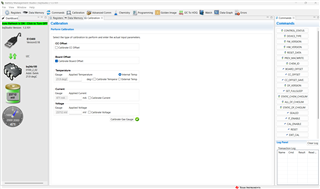
1. current offset issue:

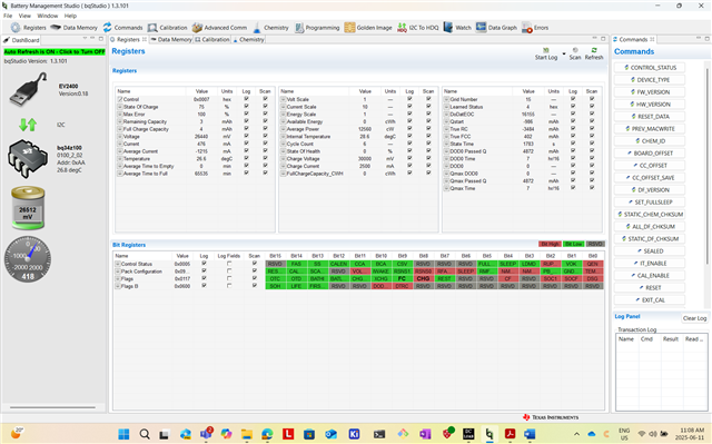
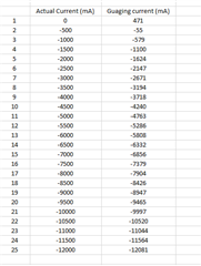
I suspect there is some BQstudio configuration issue because I always found there is a ~400mA current offset in the dashboard (attached below) without any charger and load connected. If I calibrate it to 100mA (I can't enter 0 mA, it will show an exceed range), the CC Gain will be a wrong number (~10). If I discharged it at 10A and calibrated it at -10A, the CC Gain and CC delta would be 0.486, which is quite accurate as the shunt resistor is 0.5mohm. so I keep CC gain and CC delta are 0.486 but there is ~400mA offset in the relaxation phase. I measured it actually ~0A by multimeter, Could anyone who has experience help me with that?

2. Chem-ID issue

I am also confused about the parameter configuration for the learning cycle. I am using 8s 24V, 50Ah, 128Wh, LFP battery. However, I don't know the accurate Chem-ID, I selected Lishen-LP44147132(50Ah)-0436-LFP, which has probably similar status. My colleague told me that exact ChemID is not very necessary for the learning cycle, a similar one should be good enough. I am not sure it is really unnecessary because I read it looks necessary in the TI document. I have contacted CANBAT support to see if they can provide chem-id or cell information.

3. SOC/Capacity monitoring issue in Bqstudio

The issue that I found is that when battery is actually 0% SOC, the BQSTUDIO shows 100% , when the battery is actually 100% SOC, the BQSTUDIO shows 0 SOC. After fully charged+2 hours relax, update never became 05, (it was 04). and the remaining capacity and full charge capacity are always strange number. I also attached the log file with the last fully charging and relax. You can see that SOC always keeps 100%.  

4. Current scale question

Since I cannot enter 50 000 mAh in the register of Bqstudio, it is too large, so I used the current scale as 10, which means all the values related to the current need to divide by 10, like energy, capacity, and kinds of currents. However, for the current value I can directly read from the dashboard or registers, do I need to multiply 10? Since there is ~400mA in the dashboard without load and charged connected, if I multiply 10, which is 4A, so crazy.

Could anyone help me with those issues or questions and provide me with new ideas?

Thank you!

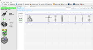
Here are the parameters I am setting:

Current scale: 10

Voltage scale:1

Energy scale:1

Number of series cells: 8 - I also set VOLTSEL =1

Design voltage: 3600mV

Design capacity: 5000mAh (scaled 10)

Design energy: 1280cWh (scaled 10)

Charge Termination Taper Current: 600mA (scaled 10, C/10, C=50Ah)

Cell Charge Voltage TX-TX-1: 3750mV: (Max charge voltage is 29.2V, but I measured the fully charged voltage will be 28.6V, so 28.6/8=3.75V)

Flash Update OK cell voltage: 2800mV: (22.5V at 0%SOC, so 22.5/8=2.8V)

Cell terminate voltage: 2800mV

Dsg current threshold:: 500mA (C/10, scaled 10)

Chg current threshold: 550mA (C/10, scaled 10, but should be lower than taper current, I know I have current offset issue, so I make this value higher that offset current)

Quit Current:250mA (should be lower that Chg/Dsg current threshold, C/20)

Cell V at Chg term:3750mV

 CHARGING_06102.log

  • Hello Jiaqi,

    This question has been assigned to a battery gauge expert and we will follow up with a response.

    Thank you,
    Alan

  • Thank you so much!

  • Hi Jiaqi,

    1) Are you using the EVM or a custom PCB? The Board offset/CC offset routine may be able to correct this error.

    2) 

    My colleague told me that exact ChemID is not very necessary for the learning cycle, a similar one should be good enough.

    This is technically correct, if the DOD error is too large the learning cycle will fail. I recommend using GPCCHEM tool to identify what the closest chemid match we have in our database.

    GPCCHEM Application software & framework | TI.com

    Simple Guide to Chemical ID Selection Tool (GPC) (Rev. A)

    3) Let's ignore SOC until we have, 1 get a chemid match, 2 calibrate correctly, 3 complete a learning cycle (including setting parameters correctly)

    4) No, the current reading is not scaled. Only parameters in ma/A/mah/etc need to be scaled by current scale. Units in W.Wh are scaled by energy scale.

    Regards,

    Diego

  • HI Diego,

    Thanks for your reply. Can I use GPCCHEM for the closest chemid before I calibrate the offset current? I am not sure if the ~400mA offset current will influence the result.

    1) I am using a custom PCB with BQ34Z100R2, which keeps almost the same layout based on the TI datasheet. I did many times CC offset and Board offset calibration, but nothing changed, can I ignore those ~400mA offset currents? as the CC Gain is accurate with shunt resistance (0.5m)?

    2) I agree, I will use the GPCCHEM tool for the correct chemid. I noticed that all the data it needs are current, voltage, temperature, and number of series cells. Can I upload those data without offset current corrected? as I think waiting for results takes time, I wanna fully take advantage of the time. One more thing needs to be noticed, I was just updated that the battery is 8s2p, any influence on GPC results? 

    3) I understand, but same question: 1 get a chemid match, 2 calibrate correctly, can I calibrate the current offset after GPC? any influence?

    4) Understood.  additional question, since the battery is 8s2p. so the taper current needs to be (C/10)/2 because one cell will be half of the total current? and the CHG/DSG current threshold should be divided by 2,  does my understanding correct?

    I would appreciate it if you could provide any ideas.

    Thank you so much.

    Jiaqi

  • Hi Alan, 

    I saw this question showed "TI Thinks Resolved", but it's not resolved. Do I need to repost?

    Thank you

    Jiaqi

  • Hi Jiaqi,

    No need unless you click "TI resolved", then I will not get a notification that you have replied.

    1) No, because the current reading is used for the impedance track calculation. If the current reading is wrong SOC will be incorrect. Try manually editing CC gain until the current reading is accurate.

    2) 

    Can I upload those data without offset current corrected?

    No, we need to correct the current reading first.

    One more thing needs to be noticed, I was just updated that the battery is 8s2p, any influence on GPC results? 

    No, change as long as the config file reflects this.

    3) No, we need to correct the current reading first.

    4) All current (ma/mah/etc) values should take the cells in parallel into consideration. Meaning for example if the capacity of 1 cell is 1000mah and the battery pack is 2p, then the value entered for design capacity should be 2000mah. 

    Regards,

    Diego

  • Hi Diego,

    Thanks for your reply. So for now the highest priority is to correct the current offset. I am very frustrated because it makes all processes inaccurate. Could you please check the setting for me to correct the offset? Here is my process to have current offset issue:

    1. I disconnected all the chargers and load, and there should be 0 current, However, it shows as an attached figure, 471mA, I also measured the actual current by current meter, it should be a few milliamperes almost 0A.

    2. I calibrated CC offset, succeeded; Then calibrated Board Offset; succeeded; However, 471mA offset current always shows there...

    3. I connected the electronics load and discharged at 2A, then calibrated at -2000 mA, and succeeded; The CC Gain and CC delta updated to 0.486 mohm, which is good because my shunt resistance is 0.5mohm. I showed my screenshot here. CC offset = -1429; Board OFFSET = -17

    4. I disconnected the load and charger again. 471mA offset current always shows there. According to your suggestions, I tried to manually update the CC Gain to make the current closed to 0. When CC Gain is 4.5, the measured current is 52mA, which looks acceptable. I calibrated the CC offset and board offset again, looks like nothing changed. However, when I connected the electronics load and discharged at 2A, the measured current showed -200mA, which is obviously wrong. After I calibrated the current at -2000mA, the CC Gain becomes 0.486 again.

    5 during all the above processes, CC offset's value is around -1430 and Board offset's value is -17 all the time, looks never changed. so I suspect if the cc offset and board offset don't work? How to fix it?

    6. I calibrated the current at 10A discharging, I compared the actual current and measured the current from BQSTUDIO. you can see that the offset will be reduced until the current is -10A, then increase. Do you think what's reason cause it? I attached the comparative table and screenshot, I am not sure if you can see them, the table and screenshot have the same content.

    Actual Current (mA) Gauging current (mA)
    0 471
    -500 -55
    -1000 -579
    -1500 -1100
    -2000 -1624
    -2500 -2147
    -3000 -2671
    -3500 -3194
    -4000 -3718
    -4500 -4240
    -5000 -4763
    -5500 -5286
    -6000 -5808
    -6500 -6332
    -7000 -6856
    -7500 -7379
    -8000 -7904
    -8500 -8426
    -9000 -8947
    -9500 -9465
    -10000 -9997
    -10500 -10520
    -11000 -11044
    -11500 -11564
    -12000 -12081

    I really need help with this issue.

    Thank you so much!

    Jiaqi Yuan

  • Hi Jiaqi,

    Can you provide your .srec I will try to replicate this on my end. 

    Regards,

    Diego

  • Hi Diego,

    Hardware has corrected the current offset issue. After calibrated, I want to confirm if my following configuration of the BQstudio is correct. The battery is 24V 50Ah 1280Wh 8s2p; The cells used are 3.2V 25Ah in configuration of 8s2p. I am not sure design capacity should refer to 50Ah as battery package or 25Ah based on cell?

    Current scale: 10

    Energy scale:10

    Voltage scale:1

    Number of series cells: 8

    Design voltage: 3600mV

    Design capacity: 5000mAh (50 000mAh/currscale) or 2500 mAh (25 000 /10)

    Design energy: 12800cWh (1280 00 cWh/energyscale)

    Charge Termination Taper Current: 500mA (C/10/currscale)

    Cell Charge Voltage TX-TX-1: 3750mV

    Flash Update OK cell voltage: 2800mV

    Cell terminate voltage: 2800mV

    Dsg current threshold: 400mA (<500mA, C/10/currscale)

    Chg current threshold: 400mA (<500, C/10/currscale)

    Quit Current:200mA (<C/20/currscale)

    Cell V at Chg term:3750mV

    Could let me know if there is anything wrong?

    Thank you

    Jiaqi

  • Hi Jiaqi,

    The Taper current is specified by the charger. Configuration looks good in my opinion; I see no obvious errors.

    Regards,

    Diego

  • HI diego,

    Thanks for your reply.

    1. I read another post and am confused about the design voltage. Should it be the maximum charge voltage of the battery package or cell? The max cell voltage is 3600 mV, and the max battery voltage is 28800 mV, so the design voltage is 28800 mV (3600*8)? 28000 or 3600, which one is correct? I am confused because it shows "Design Voltage = (number of series cells) x average cell voltage" in the document "How to Complete a Successful Learning Cycle for the bq34z100".

    2. My battery is 8s2p, 50Ah. The cell capacity is 25Ah, 2p is 50Ah, and the Nominal cell voltage is 3.2V, so the design energy is 3.2*50=160Wh or 3.2*8*50=1280Wh. Should I consider the number of series?

    3. My FC Set% is 100%, I read another post that it should be -1. Do I need to manually update it to -1%?

    I am looking forward to your reply

    Thank you

    Jiaqi

  • Hi Jiaqi,

    Use 3600mV for design voltage.

    Here is the formula for design energy: (17) How to calculate design energy for Bq34Z100-G1 - Power management forum - Power management - TI E2E support forums

    Regards,

    Diego

  • Hi Diego,

    Thanks for your reply.

    I am so confused with design voltage. The link you sent me using cell voltage, but there is another thread using battery voltage and voltscale https://e2e.ti.com/support/power-management-group/power-management/f/power-management-forum/1482069/bq34z100-g1-design-voltage---learning-cycle-importance?tisearch=e2e-sitesearch&keymatch=DESIGN%2520VOLTAGE#

    I am not sure which one is true. could you please explain it more?

    I am looking forward to your reply.

    Thank you

  • Hi,

    Thanks for pointing this out to me, this thread is wrong, I will get it deleted.

    Please follow the instructions I provided.

    Regards,

    Diego

  • Hi Diego,

    I set the design energy is 16000 cWh (50Ah x 3.2V), however, the available energy is still the default max 32767 cWh. Do you know why? I have completed the learning cycle, and the SoC reading, FCC are correct. The available energy register reading is incorrect. I posted it in this thread. BQ34Z100-R2: Available energy reading issue after a complete learning cycle - Power management forum - Power management - TI E2E support forums Could you help me with that?

    Thank you

    Jiaqi

  • Hi Jiaqi,

    Are you using a constant power model or a constant current model? (Load mode Load select)

    A log file of the error would be helpful as well.

    Regards.

    Diego

  • Hi Diego,

    The load select is 1, Load mode is 0. Here is the log file. The SoC, Voltage, current, and capacity are correct, but the available energy is wrong. 2604.cycle.csv

    Thank you

    Jiaqi

  • Hi Jiaqi,

    If you are concerned with available energy, please switch to a constant power model. Please also review all parameters in W/Wh/mWh/etc in your configuration and verify that they are correct. Please share a new log and .gg file once these changes have been made.

    Regards,

    Diego

  • Hi Diego,

    My problem has been solved. I should set the energy scale.

    Thank you

    Jiaqi